
by SV3ORA
Ultra
wideband sinusoidal VFO with AM capability
by SV3ORA
How about a universal sine wave VFO with extreme tuning range (DC-144MHz), oscillating on the fundamental frequency (no mixers), amplitude steady throughout all bands, adequate stability and only one coil changing per band? I have build this oscillator and it worked at first time. I really like schematics that do work at once, since I do not spend time without results. This circuit worked both on "ugly" construction as well as on construction on a proto-board.
This is all about a VFO 30KHz-30MHz oscillator out of an expensive old signal generator and I found it to extend to much more frequencies. I replaced the 100pF variable capacitor with a 700pF and the frequency range extended down to 20KHz. Also not so many band switching coils were needed using this capacitor. I used just 7 coils to cover 20KHz to 30MHz. I have managed to make this oscillator work up to about 55MHz using other air wound coils and by replacing the 15pF capacitor with a 100pF. Then I reach the limit of my frequency counter. Just try almost every coil to see the range. I am pretty sure it can go higher in frequency if using UHF building techniques and appropriate coils but I did not test it at the time.
The oscillator can extend much lower too if you use bigger capacitor or greater inductance coil. At 6.5KHz the sinusoidal was highly distorted but I used a small transformer primary as a coil and I did not manage to optimize the circuit for such low frequencies.
The sinusoidal signal has good shape and it is very amplitude steady throughout all bands. The oscillator oscillates on the fundamental frequency and no mixing techniques used to achieve wide range. This ensures good spectral purity without the need for variable or switched filtering. Although LPF is a good idea, I did not noticed any harmonics on my Tektronix 491 spectrum analyzer fed with a 60dB attenuator on it's input, but maybe they were too attenuated to detect.
The voltage at the output of LM317L must be +7V only, for low sinusoidal distortion. Set the 2K2 potentiometer at the LM317L regulator at about 1.2K to obtain this voltage. Then the regulator will maintain this output voltage as long as it is fed by an input voltage greater than 8.5V. The circuit current consumption is about 20mA. The VFO shows some frequency drifting, especially in the higher frequencies but I bet this can be minimized using more rigid construction, good quality ceramic coils and brass or silver plated high-Q variable capacitor. I believe that temperature stabilizing would worth it too. If you put an audio signal at point MOD you can AM modulate the oscillator.
You can use this oscillator in almost all the RF constructions. As a local oscillator for very broadband receivers, as an oscillator for very broadband transmitters, as a sinusoidal function generator, as a wideband VCO (by replacing the variable capacitor with a varicap, e.g. BB212) for a PLL controlled oscillator, as a sweeper since it is amplitude steady throughout all bands etc.
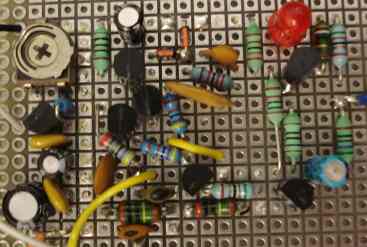
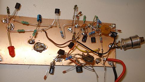
The oscillator made on proto board for more rigidity is shown above (without the LC). The components may seem far apart but they are in the right positions to ensure a minimum point to point wiring and short leads.
I was so much fascinated about the range of this VFO, so that I have decided to enhance it even more. Below are my enhancements. Click the image to download the super resolution BMP source.

The regulator is based on the thrifty voltage regulator. This is a very voltage-stable circuit like the LM317. The advantage over the LM317 is that it can supply current even if the source voltage is as low as the input voltage and it also uses discrete parts. I have been notified that such a regulation can be less noisy than the 3-terminal regulators as well. Just connect an input voltage of greater than 7.5V on the input and you get a clean regulated voltage of 7.5V at the output.
I have to admit that I did not have much success in driving the VFO using a BB212. The signal was distorted and the range was not what expected. It may be due to my not optimal setup for voltage feeding of the varicap. Nevertheless a good variable capacitor isolated from "hand effects" will give optimum results.
The range and the smoothness of tuning, depends on the value and the tuning mechanism of the variable capacitor. Initially I used a 700pF variable capacitor with a 2-turn reduction drive and the range was much extended on each coil combination, but it was more difficult to finely tune it (although not that hard). For AM it was more than ok, but for SSB it was a bit hard to tune. In that case, the cheapest solution is to use another smaller capacitor in parallel to the big one, to fine tune it. Then I used a 365pF capacitor with a 20-turn reduction drive. Although the range was more limited, this fact, as well as the huge reduction drive, resulted in a very fine tune of the oscillator. SSB stations could be easily and smoothly tuned just like my Sangean ATS-818.
If you really want a good oscillator, you have to isolate it from any "hand-effects". More important than super stability, is to ensure that the oscillator will not change it's frequency if you place your hand close to it and especially close to the variable capacitor. The way I prefer to do this, is to shield the circuit into a rigid metal enclosure and connect the enclosure to the ground. Notice that the variable capacitor is grounded on one end. You have to ensure that the shaft of the capacitor is connected to the ground and not the other way round. Just screw the capacitor to the front panel of the chassis. Chassis isolated capacitor techniques are not good and are not needed here. Even with the shaft grounded you may still be able to detect minor frequency drifts due to "hand-effects". To completely eliminate this, place the capacitor near the back panel of the chassis and use a bakelite extension rod or other hard plastic material (for tuning rigidity), to extend the capacitor shaft to the front panel. This technique is the best in my opinion and it completely eliminates "hand-effects" drifting during tuning.

Final schematic of the oscillator
I did not like very much the LED-based constant current source at the buffer amplifier of the oscillator. Different maker LEDs can have totally different characteristics and these characteristics may vary significantly by ambient light intensity and temperature. The word "LED" does not describe the characteristics of a LED, whereas the word "BC547C" does describe the transistor characteristics in a more predictable way. I preferred to use a better circuit, that is more temperature stable and has more predictable characteristics. The improved circuit, uses a matched BC547 transistor to provide a constant current to the amplifier FET. The current was kept almost the same as the previous schematic, whereas the emitter resistor reduced a bit. The voltage at the collector of this added transistor was a little bit lower but this did not affect the output waveform at all.
An oscillator to be useable, needs to have an output level suitable to drive at least a mixer. Two cascaded amplifiers have been added, to bring the level up to about +8dBm, just suitable to drive an SBL-1 mixer or other suitable diode mixer. The amplifiers are very broadband and their topology is like MMICs but made out of discrete components. A constant current source, made out of two transistors, drives each amplifier. The current source is very similar to the one described above, but now it sources current instead of sinking.
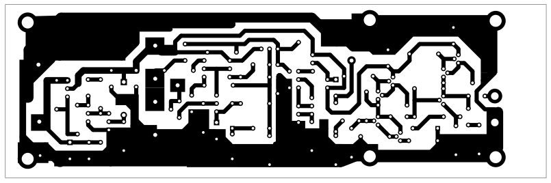
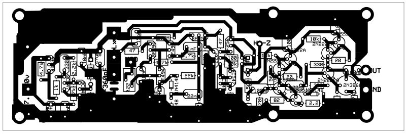
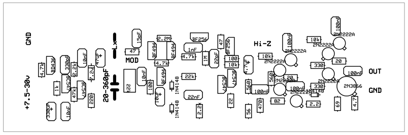
I have produced a single-sided PCB for the oscillator, to ensure a more rugged building and easier construction. The Lx and the variable capacitor are mounted off the board using short length wires. Alternatively, you may choose to use a trimmer variable mounted on the board or have a multiple switch to select different coils to cover different bands.
UPDATE 4-12-2013
Soon or later, I needed to combine this oscillator with a reverse sawtooth linear ramp generator to make a RF sweeper. This is how I did it.
I did not include the final amplifiers since I did not need such a high level signal. A single zener was sufficient to stabilize the voltage, since the input voltage in that case was a stable 12v supply. The variable capacitor is removed and a combination of a varicap and a 100nF capacitor changes electronically the frequency of the oscillator, converting it into a VCO. Note that the 15pF capacitor has also been changed to 100pF to increase frequency range. The varicap/capacitor combination that I have used, directly replaces an about 20-600pF variable capacitor, for maximum sweeping range. The switching coils are still used to set the "frequency band" of the oscillator.