
A broadband concept receiver that will amaze you
designed by sv3ora
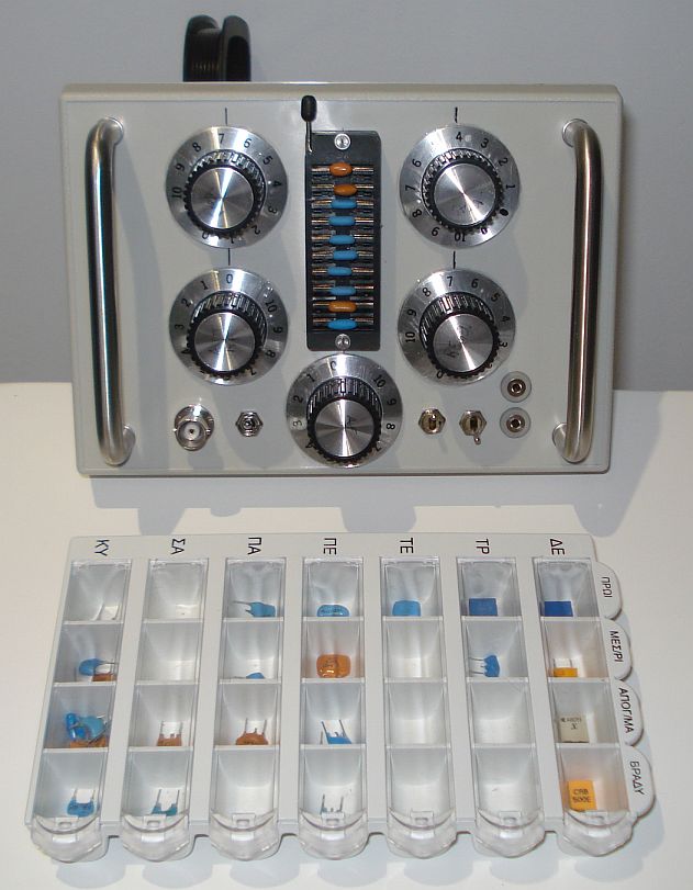
An overview of the receiver along with a pills holder to store the various resonators
A concept
circuit is definitely not a common thing among homebrewers. Most of the
builders, usually build more classic circuits that satisfy their needs
without experimenting further. Eventually someone comes up with an
unusual idea that is worth it to try. When this idea works, it becomes
a building block in our next homebrew gear. The receiver presented in
this article is such a concept circuit, as it allows for broadband
single signal (USB) reception, but at the same time avoiding the extra
complexity needed by circuits with similar features.
Here is the reflexed regenerative receiver front end that is simplicity itself, yet capable of remarkably good performance, better than any simple receiver I have built so far. The highly sensitive, single signal capable, all-bands receiver, can be easily built in a few afternoons, and it is capable of receiving any frequency on HF (1-30MHz) by just replacing the crystal for that frequency. No other components need replacing or rescaling apart from the crystal itself.
The
receiver can work on crystals, ceramic resonators (2-legs) or ceramic
filters (3-legs). The oscillator works with L/C
combinations too (in place
of the crystal) but this is something I have not fully optimized yet.
If
ceramic filters are used, you can ground their center pin, or you may
leave it unconnected. Note that crystals can achieve single signal
reception at all bands in this circuit but the sensitivity gets lower
(depended on the crystal properties) than when using ceramic
resonators. Single signal reception using
ceramic resonators, has been tested up to about 17m successfully but on
higher bands I did not have any ceramic resonators to test this. With
crystals, it works to 10m ok. Note,
that some ceramic resonators I had, refused to oscillate but most of my
other ones did, so do not get dissapointed if the receiver does not
work at first time, just try another ceramic resonator. With crystals
there is no such problem, but if you find the sensitivity a bit low
with crystals, you can try decreasing the 10k fixed resistor at the
JFET source.
The
receiver front-end 3.3mH


9v
10k
LOG
9v
100nF
100R


100k
4.7pF NP0
4.7k
100nF
J108


220k

MV209

470k
150pF
NP0

2SC
9018
![]()
100k
LIN

47pF
SW1b

SW1a


10k10k
LOG
100nF
3.3mHAFout


The receiver front-end, suitable for direct connection to the PC microphone input or high impedance headphones.
To come
up with a circuit with so low components count and good performance,
one must think cleverly. Both stages of the receiver, are used in more
than one ways. The 2sc9018 is an untuned wideband RF preamplifier with
RF gain control and an
audio preamplifier at the same time. The J108 is a self oscillating
regenerative detector.
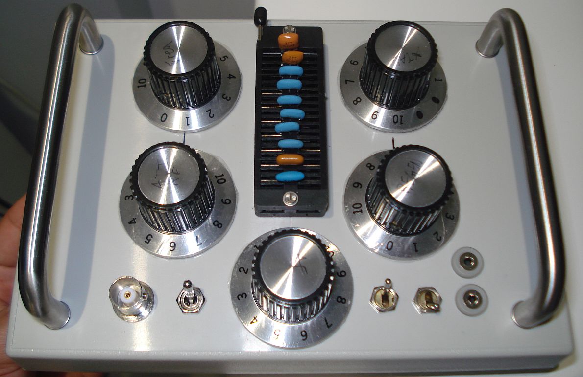
The front panel of the receiver
The receiver works the following way. RF signals come in from the antenna to the 2sc9018 RF preamplifier, where they amplified and passed to the 4.7pF and 100nF capacitors. The small portion of the RF signal that passes through the 4.7pF capacitor (small capacitance so as not to affect the tuning range, for isolation of the oscillator from the RF preamplifier and also for small loading of the oscillator tank circuit), passes through the crystal to the self-oscillating regenerative detector J108. This self oscillating mixer, mixes it's own-generated signal with the incomming RF input signal and produces audio (apart from other frequencies). The amount of regeneration is adjusted by the 100k potentiometer. The regeneration potentiometer also acts as a frequency fine tune. Especially if ceramic resonators are used, zero beating of an SSB signal might be tricky with just the frequency adjust potentiomerer (an expensive multi-turn potentiometer is not used), so fine tuning at a small amount, is performed by adjusting the regeneration potentiometer. The amount of frequency pulling from the regeneration potentiometer is small but adequate for zero beating. The output signal (RF and detected AF) out of this stage, passes through the 10k isolation resistor, the 100nF DC-blocking capacitor and the 3.3mH RF filter choke, to the 2sc9018 transistor once again (when reflexion is switched on), where it is re-amplified. Only the AF signal is amplified, because RF is blocked by the choke at the base of the transistor. This choke serves also to block RF from the antenna to pass to the regenerative detector. The amplified AF signal is then passed to the 4.7pF and 100nF capacitors and the other 3.3mH choke. The 4.7pF capacitor and the crystal after it, do not allow audio to pass through it back to the J108, so most of the amplified audio is passed through the 100nF capacitor and the series choke, to the output of the receiver. The 100nF capacitor, also passes amplified RF signals from the antenna and the 2sc9018, so the choke is used in series with it, to block RF from passing to the audio output of the receiver. If you connect high impedance headphones to the receiver or if you build the active AF filter shown later on in this article, you may remove this extra choke, as the headphones cannot respond to RF anyway and the filter will filter RF. The values of both chokes are not critical and you can use any values (even different values for both) as long as they are in the low mH range. I used two cheap molded 10mH chokes I had available. Using a separate stage as an RF (and AF) preamplifier ensures isolation of the antenna from the self-oscillating detector. There is no LO leakage to the antenna and no detector detuning.
The
output of the receiver, can be connected directly to high impedance
headphones (volume is more than adequate when a big antenna is used and
when reflexion is switched on) or it can be connected to the microphone
input of a PC. There are numerous
of programs that can then be used to further manipulate the audio
signals, filter them and decode them to meaningful data, so the
receiver does not need to be any more complex than that. However, you
will need a good processor and sound card if you want to minimize
latency due to the CPU-demanding DSP processing.
I have built this circuit numerous of times and it always work. I have built different variations, with variable capacitors, varicaps, multi-turn potentiometers or even LDRs. It always worked as expected. Note however, that when the reflexion is switched on and under the prescence of strong out of band broadcast signals, the B-E junction of the 2sc9018 is working as an AM detector! Effectively it is a diode across the antenna input and it couples directly to the AF output without any filtering at all. I am affraid, this is the price you have to pay when reflexing such a simple circuit. Bear in mind that the circuit has no RF front end tuned circuits so it is as wide band as it's possible to be. The good news, is that the detected AM signals, do not appear at all times, but only when an external untuned antenna receives very strong broadcast stations and when the RF gain is set to maximum. On tuned or small antennas, the problem should not be noticed. These detected AM signals, usually appear at quite low levels at the AF output in comparison to the wanted regenerated signals and they are mostly noticeable when they are of high levels and when the regenerative detector is not oscillating or when there are no HAM band signals tuned in. Practically, they pose no significant problem in weak HAM signal reception. Think of the sensitivity of a crystal set, with a silicon diode instead of a germanium one and you will get an idea of what I mean. No to mention, that if AF filtering is used after the receiver (be it hardware or FFT) the AF bandwidth of these 6KHz or so signals, is decreased at 2.5KHz or whatever your filter bandwidth is. On narrow band audio filtering (digital modes) these AM signals dissapear due to the narrow bandwidth and their low level. Either wideband or narowband, the RF gain control can help in reducing these interfering AM signals (but also the wanted ones).
How about single signal reception? This is a feature that only complex receivers have. However, despite it's simplicity, my receiver is capable of single signal reception. The regeneration can be set so fine, that you can adjust it to be effective on one sideband and not effective on the other. To understand this better, suppose you receive a DSB signal (both sidebands tone modulated). By careful adjustment of the regeneration, you will receive a tone on the USB and just a hiss on the LSB. The hiss will be like listening to an SSB modulated signal on an AM receiver. Not only that, but the received hiss on the LSB will be much attenuated, as a result of the lack of regeneration effectiveness on that sideband.
I tested this feature using crystals and ceramic resonators and I did achieve single signal reception on all HF bands using crystals and up to about 17m using ceramic resonators. I did not have any ceramic resonators above 17m, but I suspect it will work too. I do not think single signal reception has to do with anything related to crystal filtering of the incoming RF signal. It was only when I set the regeneration carefully, near the point of oscillation (at each frequency setting) that the opposite sideband (LSB) was rejected. It is actually not rejected, but it is attenuated and the detector is not effective in beating this sideband (attenuated AM detection only in this sideband). I verified it by setting the regeneration a bit higher and now the opposite sideband was beated (it's lower frequencies). When I set the regeneration even higher, the whole opposite sideband is beated (DSB reception). The behaviour was the same at all bands and at higher bands the setting was more "touchy" as expected, but still perfectly usable. The impressive thing is that I could do this without the need for multiturn potentiometers, which was nice, since no special parts are required now. Now this is single signal reception at all HF bands, out of this ultra simple detector! How much better can it be?
The use of the RF gain control, has interesting properties. By reducing the gain of the transistor of course, the wanted RF signals are preamplified less. However, you will practically see that without the interfering rectified AM signals anymore, you will be able to receive the wanted ones more crearly, despite of the lower RF gain. QRM and noise, is also reduced by reducing the RF gain and this helps in receiving weaker signals despite of the lower RF gain. Especially in narrowband modes, it seems most of the signals find their way to your ears, as the noise is less and the ear fatigue less.
The receiver front end (two transistors near the selector switch)
Up to
this point, I have talked for the receiver as being a reflexed
regenerative circuit. With the use of a single stwitch (SW1), the
reflexion can be switched off instantly, so the receiver then becomes a
pure regenerative circuit without being reflexed. I thought it would be
nice to switch instantly between the two circuit configurations to see
the differences, so I left the switch there. In the un-reflexed
configuration, the output audio volume is less, but there is no significant problem
from the B-E junction rectification anymore, even when the RF gain is
set to maximum, as any rectified audio is
filtered by the low value of the coupling capacitor (4.7pF) and it does
not pass to the regenerative
detector, or the AF output of the receiver easily. When tested with ceramic
resonators, switching the reflexion on or off, causes some instant
frequency
pulling apart from change in the audio volume. Also, when the reflexion
is switched off, changes in the RF gain, cause a minor frequency
pulling (not too significant). Fortunatelly, the RF gain, is not
something that you would want to change
too often. When the reflexion is switched on, there is no frequency
pulling at all when altering the RF gain.
There is
an interesting article published in this magazine
at page 15, which describes the effect of the variable capacitor in the
frequency pulling of the crystals in such a circuit. Indeed, my
experiments agree with this article, the variable capacitor that was
initially used, had the
greatest pulling effect when it was set at the lower capacitance values
and its minimum capacitance value is important.
This makes tuning more difficult at these settings, also because of
stray capacitance that has now a greater effect in frequency pulling.
If one is to avoid decade capacitors and lots of switches, two things
can be
done to limit the problem. One way, is to use a variable capacitor with
reduction gear and offset shaft position. The reduction gear, allows
fine tuning and the offset shaft
positionworks
to reduce frequency (dial) nonlinearity by positioning the shaft
and the plates in a way that produces a linear relationship between
shaft angle and resonant frequency, which can be used to compensate for
the non-linearity of the frequency dial of the receiver. The other way,
is to use a varactor diode which has a capacitance/voltage curve that
compensates for the non-linearity, together with a logarithmic
potentiometer to control it (to improve even more tuning linearity).
Fine tuning of the varactor may be done
by a multi-turn trimmer (if you can find a logarithmic one), or an
ordinary logarithmic potentiometer combined with a big diameter knob. Just
to mention that some of these cheap
plastic tuning capacitors out of old radios may present quite low
minimum
capacitances (under 10pF) and relatively high maximum (150-250pF or
so), so they may exhibit great capacitance range and they are not to be
excluded without a second thought, as they are not detuned by driving
voltage instability like varactors do.
However,
apart from improving the tuning linearity, the use
of the varactor, has also other important advantages. It avoids stray
capacitance
caused by hand effects, so no shielding is needed. It also avoids
microphonics, it has a small size and it is very cheap. However, a good
quality, humidity and dust-free potentiometer must be used for
controlling it reliably, but this can be easily found (or replaced if
damaged) in comparison to
a good variable capacitor. Even cheap potentiometers can do a pretty
good job in comparison to a cheap variable capacitor. Remember, minimum
capacitance is important
for bigger frequency pulling, so a varactor that has a low minimum
capacitance and relatively high maximum, is prefferred, but don't go
for more than 150pF of max capacitance or so, as greater capacitance
will have a small effect on frequency pulling.
These expensive 500pF varactors, have only 20pF or so of minimum
capacitance and the pulling range above a certain point is small. A
problem with varactors, is that sometimes they are considered special
parts and they cannot be easily found in a junk box. In such cases, you
could use as a varactor, the EB junction of a BJT or a common 1N4001 to
1N4007 series diode, reverse biased of course. Their pulling
range is smaller, but they can be easily found. I would avoid using LEDs
as varactors, unless they are light-shielded, as they are affected by light variations.
In the
receiver, I used the cheap MV209 varactor, together with a 10k
logarithmic potentiometer to control it. This combination gives
excellent results. The tuning linearity is remarkaply good at all
frequencies on crystals and ceramic reconators. The tuning range for
the crystals I have tested, is about 2-3KHz or so above 40m, less at
80m and almost none at 160m. The tuning range of a
40m ceramic resonator was about 60KHz and at 80m about 30KHz or so. The
more expensive 1SV149 (500pF) varactor, despite the much higher
capacitance range, improved the tuning range of the 40m ceramic resonator
by only 10KHz or so, but the tuning linearity was suffering at the
middle settings of the potentiometer. Thus, I ended up using the MV209
varactor with the 10k logatithmic potentiometer.
Correct polarity of this potentiometer is important. Do not reverse it's connections, as this will lead to a much worse tuning linearity than the varactor's alone. You can find if you have connected it the right way, by placing the receiver fitted with a crystal, near to a commercial ssb receiver, then set the logarithmic potentiometer at middle position and zero beat the commercial receiver to the receiver's local oscillator. Then move the potentiometer shaft all the way to the right and then all the way to the left. The tone that you should hear at the commercial receiver at both ends of the potentiometer, should be roughly of the same frequency if the potentiometer is correctly connected. If not, reverse the connections of the ground and the VCC to it. Another way to find out if you have connected the potentiometer the right way, is to watch the local oscillator signal of the receiver, on a commercial receiver. If the logarithmic potentiometer is correctly connected, the frequency should decrease when you turn the potentiometer clockwise.
Correct polarity of the 10k logarithmic RF gain potentiometer is also important. Connect it, so that the RF gain is varied at equal steps along the wiper movement. You do not want an attenuator that varies most of the RF gain when the wiper is moved just a little bit.
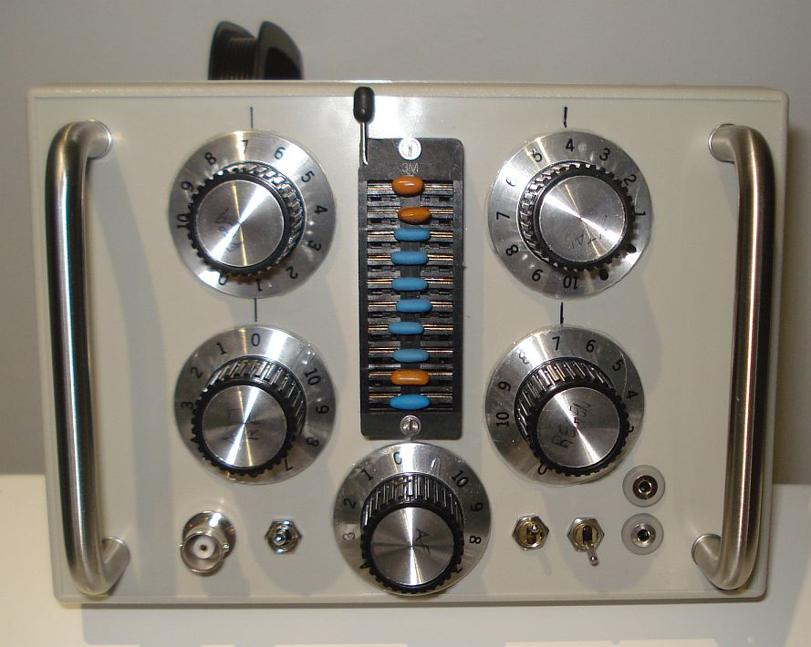
Another view of the receiver front panel
The
optional audio BPF/LPF filter for CW/SSB
| |
|
|
|
|
|
|
|
|
9v |
|
|
|
|
|
|
|
| |
|
|
|
|
|
|
 |
|
|
|
|
|
|
|
|
|
| |
|
|
10K |
|
2.2K |
220K | |
|
|
|
|
|
|
|
|
|
| |
|
|
|
|
|
|
|
 |
BC549C |
|
|
|
|
|
|
|
| |
|
|
|
 |
47nF | 10nF | |
 |
|
|
|
|
|
SW2b SSB/CW |
100nF |
AFout |
| |
|
|
|
|
|
|
|
|
|
|
|
|
|
|
|
|
| |
SW2a SSB/CW |
AFin |
|
|
|
|
|
 |
|
 |
|
|
|
|
|
|
| |
|
|
|
|
|
9v | |
|
4.7K |
|
|
|
|
|
|
|
| |
|
|
|
|
|
|
|
|
|
|
|
|
|
|
|
|
| |
6.8K |
|
47nF or 33nF |
10K | |
6.8K |
|
47nF or 33nF |
10K |
|
6.8K |
|
47nF or 33nF |
10K |
|
|
| |
|
|
|
|
|
|
|
|
|
|
|
|
|
|
|
|
|
|
|
47K |
|
|
|
|
47K |
|
|
|
|
47K |
|
|
|
| |
|
|
|
|
|
BC549C |
|
|
|
|
BC549C |
|
|
|
|
BC549C |
| |
560R |
|
47nF or 33nF |
|
|
560R |
|
47nF or 33nF |
|
|
560R |
|
47nF or 33nF |
|
|
|
| |
|
|
|
|
|
|
|
|
|
|
|
|
|
|
|
|
The optional audio BPF/LPF for CW/SSB, suitable for direct connection between the front-end AFout and the PC microphone input.
To reject nearby
signals on CW, a suitable audio BPF can be added. One could argue that
the PC sound card in combination with suitable software could be used
as an audio filter instead. However, apart from the need to carry a
computer with you, there is another drawback in this,
latency. The software needs a lot of processing power to do the job in
a short time. In older computers such a proccessing power is not
available, so there is some time taken from the time that the audio
signal enters the sound card to the time that the processed sound exits
it to the headphones. In some cases this can be as high as several
seconds. This means that as you tune to a signal, you won't be able to
listen to it unless some time has passed. Tuning the receiver to
signals is a nightmare if the latency is high. A pure analogue hardware
filter has no latency.
The three BJTs that compose the audio filter of the receiver
I have tested quite a lot of CW audio filters, LC types, regenerative types and so on. LC filter types, required quite a few hard to find inductors for the filter to be effective. The regenerative filters I have tried, required quite a few of critical adjustments in order to operate effectively. Moreover, none of the latest proved to be stable enough. Upon signal strength variations, they all oscillated violently. The CW filter that gave the best performance and stability and did not require any adjustments, is the multiple feedback band pass filter presented here. It is composed of three identical cascaded filters.The six CW filter capacitors, define the center frequency of this filter. If 47nF are used, the center frequency will be close to 700Hz. If 33nF are used, the center frequency will be close to 1KHz.
SW2,
selects between CW and SSB filters.The SSB filter does not have to be
more complex than a single stage and this filter starts to roll-off
from about 2KHz and above.
The CW filter (less than 250Hz bandwidth) gives excellent selectivity for its simplicity without any oscillations. To get an idea of it's selectivity, it is suitable for selecting just one out of the two tones of an RTTY signal. Strong CW signals that are very close to the passband can still be heard in the background, but they are greatly attenuated and do not affect the wanted signal reception, even if it's strength is lower than these. This proved to be a desirable feature when scanning the band for signals, as you can find out what is going on nearby without having to retune the frequency of the receiver. In comparison, the narrowband filter of my commercial gear, requires very slow tuning of the frequency, so as not to accidentally dismiss signals when scanning, which has been proven to be inconvenient when scanning large portions of the band.
Optional AF amplifier with automatic limiter
|
|
|
|
9v |  |
|
|
|
|
|
|
|
|
|
|
|
|
|
|
|
|
|
|
|
220R |
|
 |
22uF 16v |
22uF 16v |
|
5.6K | |
|
|
|
|
|
|
|
|
|
|
|
10K | |
|
|
 |
|
|
2.2K | |
10uF 16v |
|
|
|
|
|
|
|
|
|
|
|
 |
|
|
|
5.6K | |
|
|
|
|
|
|
|
|
|
|
|
47K | |
22uF 16v |
|
|
|
|
|
BC549C | |
|
 |
600R |
|
|
|
|
|
|
|
|
|
|
|
|
BC549C | |
510R | |
|
|
600R |
|
Input |
|
|
|
|
|
|
BC549C | |
22nF | |
200R | |
|
|
|
|
|
|
|
100nF |
10K |
|
100nF |
|
|
|
|
|
|
|
47K |
|
|
|
|
|
| 10K LOG |
 |
|
|
|
|
|
|
|
|
|
|
|
|
|
|
|
|
|
|
|
|
|
|
BC549C | |
10K | |
22K |
|
|
5.6uF 16v |
|
|
|
|
|
|
|
|
10K | |
|
|
|
|
|
|
|
|
|
|
|
|
|
|
|
|
|
|
|
|
 |
|
|
|
|
|
|
|
|
|
|
|
|
|
|
|
10uF 16v |
|
|
1N34A |
 |
1N34A | |
10uF 16v |
|
|
|
|
|
|
|
|
|
|
|
|
|
|
|
|
|
|
|
|
|
|
|
|
|
|
|
|
The optional AF amplifier presented here, has been tested with the receiver with great success. It provides a gain of about 100dB or more, which can be thought at first as too much for this receiver. However, because of the great variations in the input signal level, there are many times where high gain is needed and this amplifier provides it. For example, some of my crystals had very high losses and I had to switch the front end reflex switch to on, adding another audio preamplifier into the AF chain. Ideal signal reception is actually accomplished with combinations of the settings of the reflex switch, the RF gain the regeneration and the audio volume controls. There are some times where it is more prefferable to switch the audio gain to high and limit the RF gain. Other times, the opposite is prefferred, depended on the signal strength and the noise. But that is the beauty of this receiver, the operator has full control over these parameters, even the way detection is accomplished.
The audio amplifier of the receiver. The limiter is not shown in this photo.
I
thought that the AF amplifier would be the easiest part of the
receiver, but surprizingly this was not as straight forward as it
seems. There are various reasons for that. First, the receiver front
end audio output volume varies significantly, depended on the strength
of the signal, the way the regeneration is set and whether you use
crystals or ceramic resonators. Then there were switch "clicks" from
the reflex and the filter switches, as well as noise from the
regeneration potentiometer, when regeneration exceeds the limits (due to DC on the wiper).
Additionally, the high gain amplifier oscillated violently in high
input signal levels. If you use a speaker amplifier, you usually do not
need to worry about these things.
However when you use headphones, the situation has been found to be completely different. All those noises from the potentiometers and the switches, when amplified in this high gain amplifier, can really split your ears apart, while you are trying to dig out weak signals. The amplifier volume has to be set on high gain when you are trying to receive these faint signals. This causes the amplifier to oscillate, splitting your ears apart once again. Another thing that matters is noise. Whereas on HF, noise from the AF amplifier do not matter much, in this very quiet receiver, noise from the AF amplifier (mostly hiss) is observed in high volume, because noise is amplified as well as the wanted signal. Another point is that, for measuring signal strength effectively, you do not want an AF AGC in the circuit. In other words, you need to cut-off internal amplifier noise and the very loud noises but not the relatively strong signals.
In the AF amplifier shown, the first transistor following the input potentiometer, is used as an automatic limiter. Audio signal is taken from the output of the amplifier and drives the germanium diodes (any Ge diode can be used, because of the low forward voltage drop), which rectify it and charge the 10uF capacitor at the base of the transistor. Depended on it's charge, the transistor "opens" more or less, which affects the AF output of the voltage divider formed by the transistor itself and it's 10k collector resistor. The components values have been chosen, so that only very loud signals at the output of the amplifier (switches clicks, amplifier oscillations) can cause the limiting of the input volume. The attack time is very short, which means that the limiter responds fast to all these noises, protecting your ears. The decay time is about half a second, which allows the operator to know when these noises happen, but does not allow loosing much of the following wanted signal.
The 22nF from the collector of the second transistor to the ground, is the anti-hissing filter. Without it, the amplifier hiss is very noticeable. With it in place, the amplifier is very quiet, even in high volume settings. It also helps in preventing amplifier oscillation. Any value from 10nF to 22nF can be used. Do not go for less than 10nF as the hiss will become noticeable again. Do not go for more than 22nF because you will cut-off much of the wanted audio bandwidth. 22nF is probably too much, but I personally find it less important to cut-off some high audio frequencies, for the shake of preventing ear fatigue after hours of listenning.
The
output of this AF amplifier is high impedance (2.2k). This saves lots
of power from the battery but it also requires high impedance phones to
be used. I had two separate 600R magnetic ear plugs which I connected
in series for better audio volume. 600R phones will work too at a bit
less volume. Any high impedance phones can be used with this circuit,
but if you have the luxury, choose ones that provide maximum volume and
cause you the less ear or scull pain when listenning a lot to the
receiver. The weight of the phones and the pressure to your head is
important for this.
I did not want to cut the cable or remove the connectors of my vintage phones, so I used two female jacks onto the receiver chassis and wired the phones in series within the receiver. Because there are two series connected jacks in the receiver, connection of a computer to the receiver can be accomplished by unplugging one of the two phones and connecting the computer sound card input to it with an audio cable. This allows you to monitor the audio signal from one of the two phones, as well as from the computer, although the computer would be normally more sensitive and would require the receiver audio volume to be set at low levels.
Optional wideband small loop
active antenna
|
|
|
|
|
|
|
9v | |
|
|
|
|
9v | |
10k LOG |
|
|
9v | |
|
|
|
|
|
|
|
|
|
|
|
 |
SW2b | |
100nF |
|
100R | |
|
|
|
|
|
|
|
|
|
|
|
|
|
|
|
|
 |
|
|
|
|
|
100k | |
4.7pF NP0 |
|
4.7k | 100nF |
|
|
|
|
|
|
|
|
|
82k |
|
|
|
|
J108 | |
|
|
|
|
|
|
|
|
|
|
|
|
|
|
2.2nF |
|
|
|
100nF |
Wire ANT |
|
|
|
|
220k | |
MV209 | |
|
470k | |
|
|
| Loop ANT |
|
Square frame |
|
|
|
|
|
BF494 | |
|
150pF NP0 |
|
|
|
|
2SC 9018 |
|
|
3.3mH |
|
|
|
| 7turns | |
10x12 cm |
|
|
|
|
 |
BF451 | |
|
|
 |
|
|
|
47pF |
|
|
|
|
SW1b |
|
|
|
|
|
2.2nF |
|
82k | |
|
|
SW2a |
|
|
|
|
|
|
|
|
SW1a |
|
|
|
|
|
|
|
|
|
560R | |
100nF |
|
|
100k LIN |
|
|
10k LOG |
|
|
|
|
|
|
|
AFout |
|
|
|
|
|
|
|
|
|
|
|
|
|
|
|
|
|
|
|
|
|
|
|
|
|
|
|
|
|
|
|
|
|
|
|
|
10k |
|
100nF |
|
3.3mH |
|
|
|
|
|
The schematic above shows the core of the receiver, with the addition of a wideband active balanced loop antenna. The preamplifier power is switched off when the wire antenna is selected instead, so as to save power drawn from the battery. This design avoids the use of a matching transformer or tuned circuits, which makes it really easy and cheap to build.
The loop antenna is wound on a
10x12cm plastic square frame, with 7 turns of small diameter (standard)
insulated wire. I actually used a plastic frame from an old AM radio for the purpose.
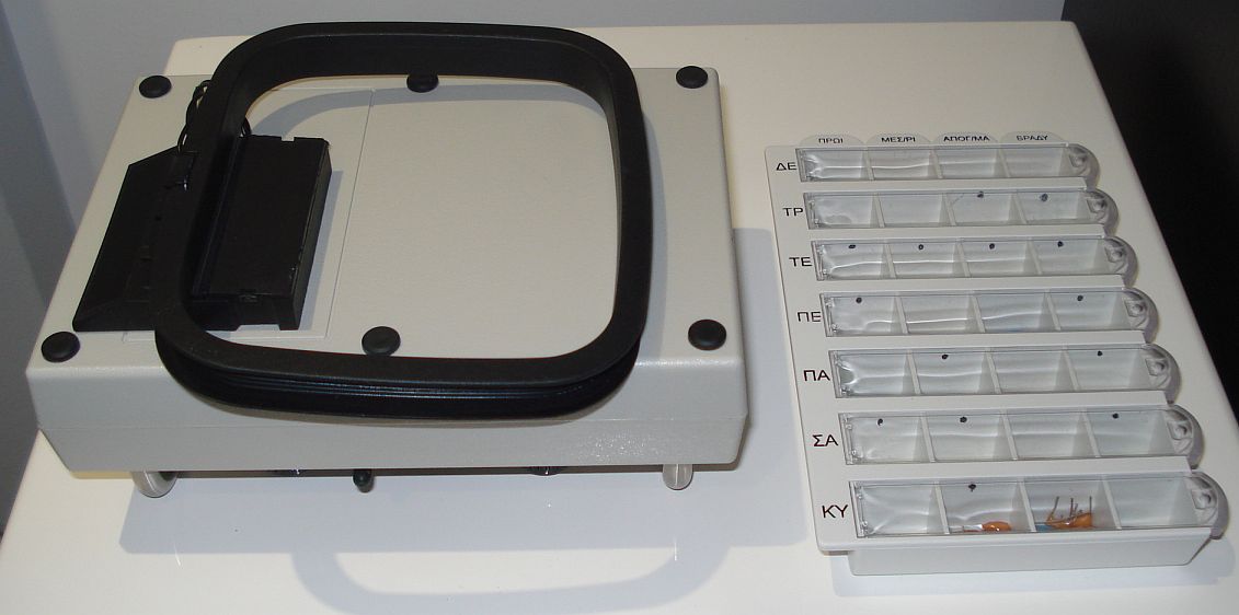
The loop antenna mounted at the back of the receiver and folded in.
This
frame allows for the antenna to be rotated at the horizontal plane,
which could be useful if the receiver must be placed in a fixed
position onto a desk. Interference can then be rejected by rotating
only the antenna frame, not the whole receiver.
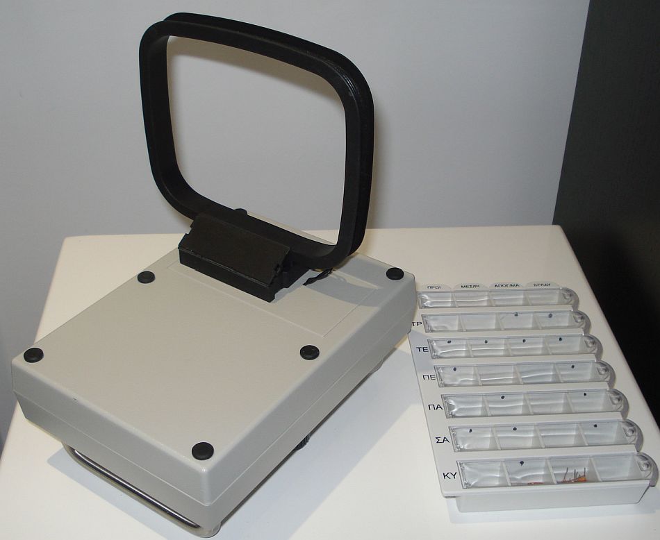
The loop antenna folded out
The active loop antenna performance is very good, considering it's small size and the small parts count. Compared to a 12m sloper wire on the roof, the 10x12cm active loop has almost the same gain and this has been tested from 2MHz and upwards. Not only that, but the loop (being balanced) is less prone to picking up local intefrerence. Apart from that, a great advantage is the ability of the loop to notch out unwanted signals or interference that comes in from a specified direction, by physically rotating the loop. With this antenna attached onto the receiver enclosure, now you have a really portable receiver that you can take with you anywhere, without being depended on large antennas anymore.
Overal construction of the receiver
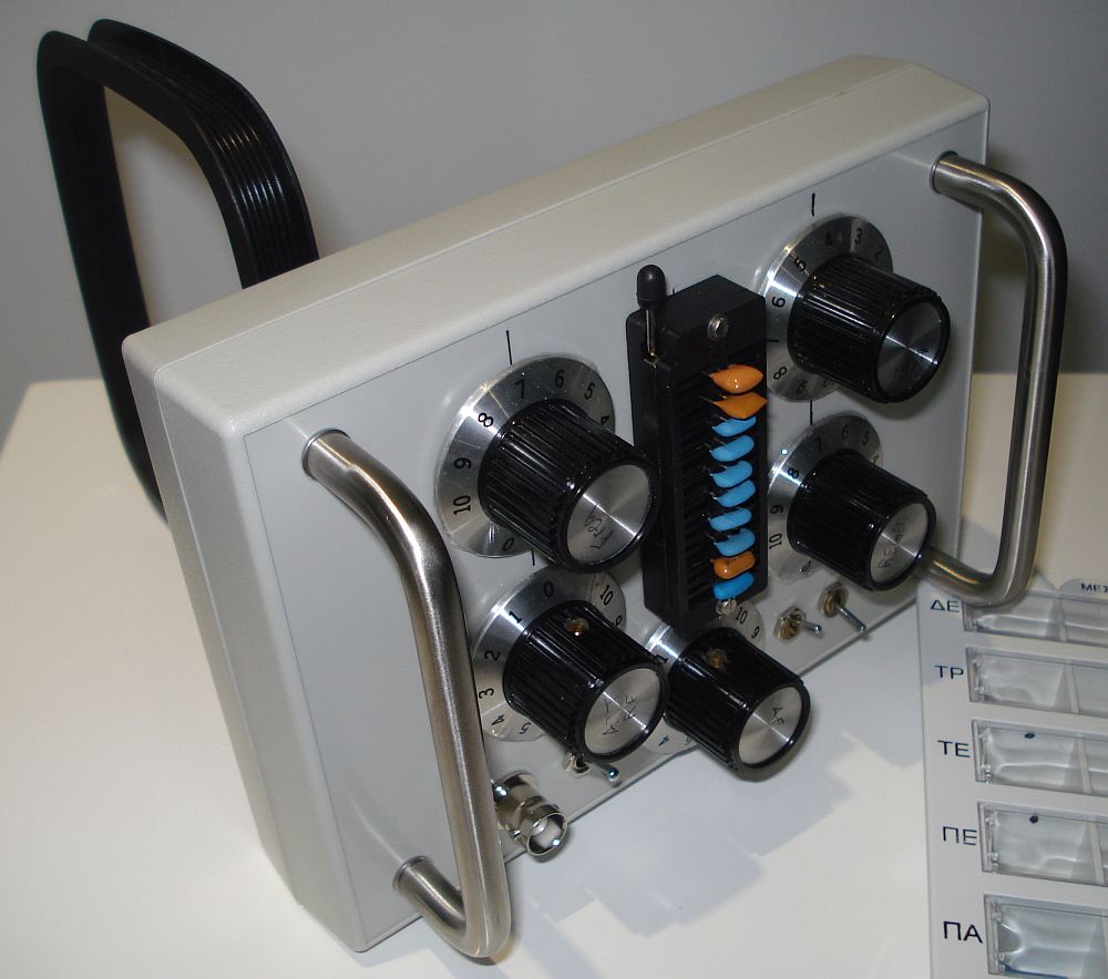
A side view of the receiver
The receiver is built into a small plastic enclosure. A metal enclosure would probably be better but this would be more difficult to drill and it could potentially interfere with the loop antenna pattern. However, some short of RF grounding and isolation from hand effects is needed and this is provided by the PCB inside the receiver.
The
knobs of the controls are chosen to be quite big (but not huge), so as
to provide some short of fine tuning without the need for expensive
vernier drives. The tuning of the regeneration is the most critical
setting and this can be very conveniently set for single signal
reception, even at the higher swortwave bands. I have whosen knobs that
have scale markings on them, so I do not need to do many front panel
markings myself.
On
the front panel, there are switches for selecting the antenna and the
audio filter type, as well as the topology (regenerative or reflexed
regenerative) and of course the external antenna connector and the ZIF
socket.
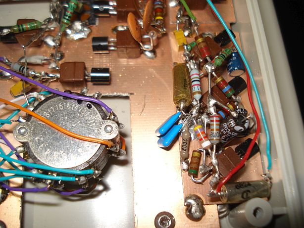
The crystal selector/resonator is a new idea. You can never have enough resonators and the receiver is designed to be broadband (cover the whole HF by just changing resonators). So simply soldering the resonators onto the selector switch is not a good idea. On the other hand, having just a crystal socket on the front panel, means that you would need to carry all the resonators with you all the time, as you go outside with this receiver on hand, which is not convenient. So I have thought of a compromise between the two and I used a ZIF (zero insertion force) IC socket to hold ten resonators. If I need to replace a resonator, or a bunch of resonators, I just unlock the socket lever and replace the resonators. Another advantage of the ZIF socket, is that the pins of the resonators do not wear out as you insert them many times into the socket. I used a 40-pin socket, which would normally hold 20 resonators, but I removed the intermediate socket pins so as to reduce the parasitic capacitance of the socket, but also to make some space for adjacent resonators.
The
way you organize your resonators onto the socket is your decision. You
may organize them by bands or by listenning preference frequencies etc.
If you organize them by bands, you may also use additional DIP sockets
(one for each band) and place the resonators onto them. When you want
to change band, you unlock the ZIF lever and you replace the whole DIP
socket which holds the band resonators. The possibilities are endless,
it is really up to you to decide the most convenient way.
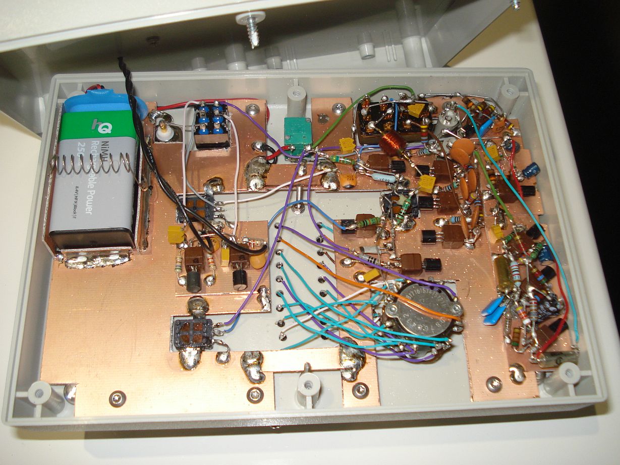
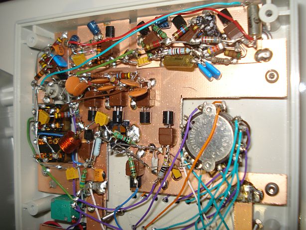
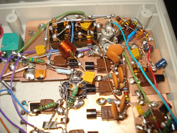
The internals of the receiver, all made using discrete components.
The
selector switch must be placed as close to the ZIF socket as possible.
I used a rechargeable battery for the receiver and I made a holder for
it out of two pieces of PCB, soldered at the sites of it to keep it in
place. A small spring prevents the battery from dropping out and allows
for easy replacement. It is important to use good quality
potentiometers on this receiver for smooth setting of the controls. I
used Panasonic miniature plastic potentiometers for all the controls
except for the audio volume. The audio volume potentiometer has also a
switch on it, which is used as the on/off switch for the receiver. I
didn't include any on/off LED as there is no need to draw extra
prescious current from the battery. The front panel handles have been
placed there so as to protect the controls if the receiver accidentally
drops with the panel faced down.
There
are not many things that can go wrong when building this receiver, if
you follow the schematic diagrams correctly. After all, there are no
hand-wound inductors and the receiver has been designed with simplicity
in mind, so as to be easily reproduccable by most radio amateurs with
basic electronics skills. Should any faults arise, do not hesitate to
contact me to provide any help I can.
Operation of the receiver
To really appreciate the features of the receiver you have to spend some time operating it. Find
some free time, maybe on a rainy Sunday afternoon, away from real life
obligations. Sit comfortably in front of your desk with the receiver in
front of you and a cup of coffee or your favourite sweet next to it.
Don't get hurry, relax and enjoy every moment of the receiver you have
built and its operation.
Bring next to you the box where you keep your resonators and plug in your selected resonators to the ZIF socket. Select the internal antenna or plug in an external antenna and your favourite high impedance phones. Switch on the power, set the RF attenuation to minimum, select the resonator of your choice and adjust the volume control for an initial comfortable noise level. Adjust the regeneration until you notice the oscillation hiss. No worry if you set the regeneration too far, as this receiver never oscillates at audio. With each resonator setting, wou will find the optimum oscillation level by noticing the audio volume on the phones (maximum is best).
I usually listen to DSB, by setting the regeneration at maximum that allows for oscillation and good audio volume. That way I do not have to continuously adjust the regeneration. It is only when near-by interference by other stations happens, that I turn down the regeneration to reject the LSB. It is easy to find the point of the regeneration control that this happens, by noticing the change in the audio response. As you pass from oscillation to no oscillation, the audio bandwidth is reduced, like when you turn down the treble on your stereo and a characteristic hiss is heard. You will still hear signal tones clearly (sometimes a bit level-reduced) on the USB at that point, but the LSB signals are gradually dissapear, starting from the higher tones to the lower, as you continue to decrease the regeneration. If you continue to decrease the regeneration, the low tones of the USB start to dissapear as well, similarly to what an audio HPF would do in place. These adjustments are a bit touchy but they can be done comfortably with a stable hand. Play around by setting the regeneration back and forth at that point, to understand the operation of how the LSB is cut-off by the appropriate regeneration setting.
Listenning on a signal, switch back and forth from the external antenna to the active loop and notice the differences in the signal level and the background noise. The RF attenuator will be useful here. Rotate the loop to see the effect of rejecting interference caused by home appliances and also to find the direction of the interference or the useful signals. Switch back and forth the active filter on narrow band signals and notice the difference on the audio responce. Upon switching to the narrow audio filter you may have to do careful fine adjustment of the frequency (more finely performed by the regeneration or even the RF gain control to some point), so as to center the signal tone to the filter peak. Switch back and forth the regenerative/reflexed-regenerative switch and notice the difference in the audio level but also the background noise.
All
these controls, sometimes even interacting together, allow you to
precisely define the way of the reception of a signal, starting from
the RF end, affecting the actual way of detection and
ending to the AF, with every stage to have it's own user selectable
settings. The combinations are endless and it is only up to your
available time to explore them. In any case, this receiver will enjoy
you not only because of it's operation and performance, but also
because of its collective character. If you happen to be a collector of
electronics components you may find it fun to try to dig-out different
rare resonator frequencies from the web, shops or flea markets to try
on this receiver.