
The fully transistorized radio project
by SV3ORA
The goal of this project is to build a complete working radio using discrete components. Despite discrete components are used this radio does not aim to be very simple in construction. Many transformers are used throughout the circuit and careful alignment must be done. A fully educational radio that will give you much satisfaction during building and when completed. I find building this radio, a more fascinating project than even building a radio amateur SSB receiver, mainly because of the lots of RF transformers used.
The basic radio
Why designing a radio from scratch when there is one already designed and tested? This saves time and cost. Elenco sells an excellent AM/FM radio kit. The building and alignment processes are described fully in the manual.
Elenco model AM/FM-108CK superheterodyne radio
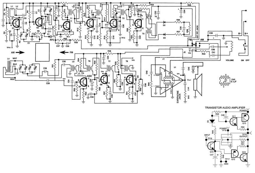
The schematic of the radio is shown below. The components list and all the necessary details to build and align the radio are given in the manual, so I will not repeat them here. I would of course build the transistorized audio amplifier. It really seems cheating to have a chip amplifier whereas building a completely discrete components radio.
The stereo decoder
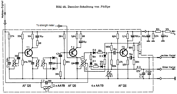
Original Phillips decoder
The four diodes in a ring are
not a mixer. To understand how it works you must first realize how the two
channels of a stereo signal are encoded. The way they are transmitted is
complicated but if I over simplify it to explain:
The left and right channels are both chopped at a fast rate then selected
alternately. So the transmission (I'm ignoring the transmitter carrier offsets
and differential channel signals) is basically a short burst of left channel
then a short burst of right channel repeated continuously. This maintains
compatibility with mono receivers which hear a combination of the two channels
as though they were one. The chopping and selecting has to be done in the
receiver at exactly the same speed and phase as it was in the transmitter so one
channels doesn't 'leak' into the others time slot. The switching has to be done
fast enough that it can't omit complete cycles at the highest audio frequency or
cause beat notes as both would degrade the audio quality. The problem with FM
transmissions is the higher frequency in the modulation is, the wider the
overall bandwidth becomes. The requirement to send a fast enough switching tone
and still use a reasonable bandwidth can't be met in the normal domestic VHF
broadcast frequency allocations. So a trick is used - the pilot is sent as a low
level 19KHz signal, just too high for most people to hear and too quiet to cause
noticeable interference to the audio. At the receiver, the 19KHz is picked out
of the received audio by using a filter, then the frequency is doubled to 38KHz
which is then used as the channel switching frequency.
In the circuit you show, the input is already converted from FM and is the
recovered audio itself. It is split into two paths, one is the audio through a
parallel tuned circuit (L2/C2) which removes the 19KHz pilot leaving only the
audio, the other is the path through T1. The tuned circuit in the base of T1 is
to accept the 19KHz and amplify it (remember it's at low level compared to the
audio). The tuned circuit in T1's collector works just like a full wave
rectifier in a power supply. The transformer is tuned to 19KHz and its secondary
is center tapped so the output from the two diodes is predominantly twice the
input frequency at 38KHz. L3/L4 is tuned to 38KHz and the baseband audio is fed
to the center tap of the secondary. The top and bottom of L4 carry 38KHz, one in
phase and the other inverted, these alternately turn on one or the other pair of
diodes in the ring so they act as switches to route the audio down one path or
the other. This gives the separated channels out. Left and right are recovered.
Now the bit where I over simplified it - Ignore this if you want to - The
signals are actually transmitted as L+R and L-R alternately, T3 does a kind of
"invert and add" operation to do the math needed to make L and R really come out
properly.
The only other point to note is that on most mono FM receivers, the
discriminator (FM demodulator) is normally followed by a de-emphasis stage. If
you build this circuit you will have to extract the audio before the de-emphasis
is carried out. The reasoning is this: In order to improve the signal to noise
ratio, the higher audio frequencies are boosted relative to the lower ones at
the transmitter, rather like turning the treble tone control up before
broadcasting. This is called pre-emphasis, to re-level the response at the
receiver, de-emphasis is applied which does the reverse, its like turning the
treble down again. It improves the SNR because the noise in the system is
independent of the audio and reducing the high frequencies at the receiver makes
it less obtrusive. Boosting before sending and lowering again the receiver gives
an overall flat audio response while still reducing the noise. This introduces a
problem though, because the de-emphasis circuit in the receiver reduces higher
audio frequencies, it also reduces the pilot level and makes it more difficult
to extract it cleanly. The fix is simple, feed the circuit from the
discriminator without de-emphasis and apply it to the left and right channels
after they have been decoded instead. This is what R3/C3 and R2/C4 do in the
circuit.
What is you want to force mono operation? The easiest way to force mono is to stop the 38KHz reaching the diode switches. I think shorting out the 33K bias resistor in the base of T1 should do the trick. The volume shouldn't change much.
Where should I take the output
from the Elenco radio in order to drive the stereo decoder? Across C23 pads. C23
is the de-emphasis (very crude!) but removing it altogether might let IF reach
the audio stages so I would leave something there, perhaps 470pF or so to work
as an RF filter.