Classic 40
A classic CW/AM transmitter based on the emtx
10-14W on CW, 4-6W on AM
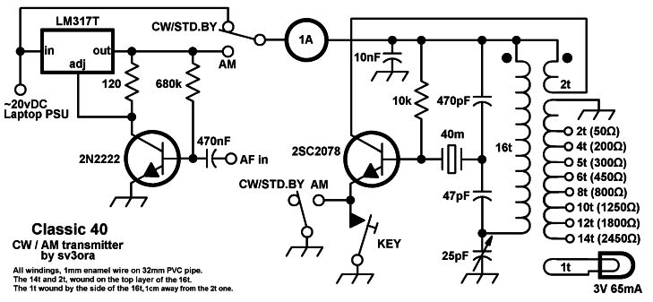
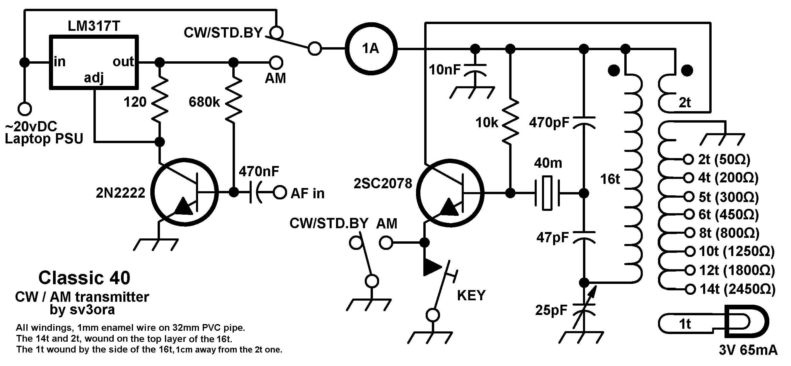
Above: schematic of the classic
40.
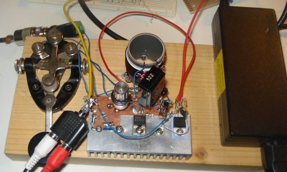
Below: Classic 40 tested on a piece of wood.
The design and the story behind it
Older ones may remember the era where transistors first came in. They
were expensive and their performance was limited at the early days
compared to the tubes. Many HAMs already building their own equipment,
the so called "novice transmitters", using vacuum tubes. There are many
such designs to look around, usually one tube transmitters that can be
built easily compared to multi-stage ones. With the passing of the
tubes and the rise of transistors, HAMs were gradually moving to the
solid state transmitters. Solid state technology, allowed more stages
to be implemented at lower cost and effort. Usually, more stages meant
better performance or more features, so HAMs went for such designs. It
seems that, with the rising of transistors, the art of minimalistic
single-stage designs was lost. The only field where single stage
transmitters continued, was the QRP homebrew equipment. However, most
of these designs were and still are, low power transmitters, 1-2 watts
the most, most of them being less than a watt. Whereas they work, they
don't have enough power to get you DX most of the times, with the
exception of when the propagation is very good, or if you have really
good antennas, which many don't. Indeed, the tube still remains the way
to get much output power on a single stage transmitter. However,
tube-related components were once easy to find but today they are more
rare and expensive. Even a single stage tube transmitter will cost you
much more than you think, if you can find the components. And whereas
you can build a multi-stage powerful solid state transmitters, it is
still challenging to built a powerful one in one stage with solid state
devices. I wanted to take this challenge, so I designed a classic
transmitter to satisfy these requirements, the "Classic 40".
The classic 40 is based on an earlier design of mine the "emergency transmitter".
In the design of that transmitter, simplicity, high power (in terms of
QRP levels), multiple input voltage, "any NPN" and "any antenna", were
the requirements. The classic 40, is optimized for maximum output power
only, using more specific components and a single voltage source,
usually a laptop SMPSU. However any CB-type power transistor can be
used in the power oscillator and you can alter the design easily to
suit your requirements.
My emergency transmitter was only CW. Then I thought, why not "give
voice" to the design? CW is good, but it is half of the fun. If you
could use your simple CW transmitter to sent your voice, this would be
great. You could now chat comfortably on the nets and have much more
fun. The simplest modulation you can apply to an existing CW transmitter, is the AM
modulation. And whereas this is an old modulation, mostly abandoned by
HAMs due to beeing inefficient, there are still AM nets on HF. AM can
can also be heard by SSB receivers by zero-beating the receiver to the
AM carrier. So you could still use your simple AM transmitter to chat
with the SSB guys.
In the old days, the most common way to apply AM modulation was to
modulate the high voltage to the plate of the tubes, using a
transformer and a powerful audio amplifier. In low voltage solid state
circuits, you can still do it using transformers, but you can also use
series transistors instead of the transformer. All these things require
many components and/or powerful AF amplifiers if one is to modulate
higher power transmitters. This does not match the keep-it-simple
philosophy of my Classic 40.
So I thought of a simple trick with the use of the extremely common
LM317. The modulator I have tested uses just 6 common cheap components
and it is able to achieve remarkably good modulation levels for it's
parts-count, just from line audio input. It juices every bit of the
internal circuicity of the LM317, just look at where the base current
of the 2N2222 comes from. For more information on the operation of the modulator, keep reading.
Following my detailed instructions, the classic 40 transmitter can be reproduced
easily,
within hours. The result is always success, this is one of the circuits
that are not critical at all and a successfully working transmitter can
be reproduced every time. I have built this transmitter several times,
using similar components (even toroids) and it always worked. The
transmitter meets the next expectations:
1. Output power (including harmonics): 10W to 14W
on CW, 4W to 6W on AM (modulation level varies with power).
2. It can drive any antenna directly, 50 ohm or higher impedance,
without external tuners.
3. Band of operation: 40m (out of band operation can be done but not allowed by regulation)
4. Modulation: AM, ON/OFF (CW, Feld-Hell, TAP code).
Components selection
The classic 40 has been designed to use only readily available
components. Most of them you may already have in your junk box. After
all, there are very few parts in the whole transmitter design. The ones
you don't have, can be taken out from various equipment, or bought even
at a modest-stock electronics shop at your area for peanuts.
The transistor:
This transmitter has been designed so that it can operate with any NPN
BJT in place. This includes small signal RF and audio transistors and
high power RF transistors like the ones used on HF amplifiers and CB
radios. However, the modulator has been optimized for usage with CB power transistors, such as the cheap 2sc2078.
Other CB power transistors are
the 2sc2166, 2sc1971, 2sc3133, 2sc1969 and 2sc2312. There are
many others. If you use another transistor or another input voltage (eg
12v), you may need to alter the values of the modulator resistors. That
is the only change you need to do in such case, as the transmitter
alone is capable of operating with any NPN transistor and any voltage
from 1.2v to 30v.
The crystal:
This is the most uncommon part of the transmitter. You have to find the
crystal for the frequency that you want to operate on. In such a single
stage design, when you operate the
transmitter at high powers and currents, you will notice crystal
heating and chirp on CW at the frequency of the transmitter. This chirp
is
not that much. You can still work stations and it can still pass
through the CW filters of the receivers. However, if this chirp annoys
you, then you have to use these vintage bigger size crystals, that can
handle more current through them. But these are evem nore uncommon. The
approach I have used in my prototype, was to connect two or more modern
crystals of the same frequency in parallel, so that the current is
shared ammong them. This improved the CW chirp at high powers just if I
was using a single vintage crystal. Again, this is optional, but if you
want to minimize chirp (and crystal heating) without searching for rare
vintage crystals, this is the way to go. On AM mode chirp is not a
problem, since the transmitter operates continuously and chirp is
unnoticeable on AM.
The incandescent bulb:
This bulb is used as an indicator of the state of the transmitter and
the modulation level. This bulb will light on when the transmitter
oscillates. It monitors the actual RF signal, so it's brightness
changes according to the amount of RF power the transmitter produces. This
is just what you need to know in order to set the variable capacitor
properly. On AM, the bulb will slightly change brightness according to
the AM modulation level. Although not as accurate as a current meter,
this monitors directly the output power of the Classig 40. Miniature
incandescent bulbs may not be that easy to find
nowadays. However, there is a good source of these, that almost anyone
has in their houses. This source is the old Christmas lights. You do
save old Christmas lights, don't you?
The meter:
In my "emergency transmitter" no current meter was used, due to cost,
components count and simplicity reasons. However, in the Classic 40 I
relaxed the rules, so now a nice 1 ampere panel meter can be used. Tune
the 25pF variable capacitor for around 500-600mA of transmitter
current. If you want more power you can push it to 700mA or even 800mA
but don't go further than that, as chirp and crystal heating increases.
Along with the incandescent bulb the meter will give you a nice
indication of a correctly tuned transmitter.
The heatsink:
The transmitter transistor does not get very hot, even on AM, so a
small heatsink should suffice. However, the LM317T regulator, being
inefficient and operating all the time on AM, requires quite a large
heatsink. If you build the classic 40 on an aluminium chassis, you
could use the chassis as a heatsink, with the appropriate insulators
and thermal paste for the transistor and the regulator of
course. The regulator package is the same as the power transistor one,
so use the same type of insulators. I like mica insulators better, but
use what you have available. The size of the heatsink I used in the
prototype is ok for CW and AM talk, but it is quite small if one is to
operate the transmitter on AM for prolonged periods of more than a few
minutes. Of course you can always use a blower, but I prefer passive
cooling for various reasons.
The AM modulator
The AM modulator used in the classic 40 is a kind of novelty. Whereas
there is nothing special in a modulated power supply, this circuit has
some interesting properties. It is amazingly sensitive and it is able
to provide lots of modulated current to any transmitter that it can
feed. It can be easily driven by the phones output of any laptop
(around mid-volume) and provide a very good depth modulation to the
transmitter. Charles Wenzel was kind enough to do a simulation on the
circuit, which is shown below.
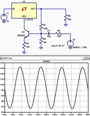
His circuit is a slight variation (for measurement purposes). The
resistor to ground on the base stabilizes the bias and the ratio of R1
and R2 set the output voltage (0.6 volts across R2 gives about 8 volts
across R1). He put in an emitter resistor just for good measure. Same
for the series resistor from the source. Charles words, "I don't know
how believable these results are but it looks pretty darned good!".
The circuit is being used as a current booster, the current being the
supply to the transmitter and dependent on the voltage it produces. The
LM317 always tries to keep 1.25V between it's output pin and "adj" pin
but where we benefit here is the current at the "adj" pin is very low,
so it is easier to apply audio to it. Effectively, the error amplifier
inside the voltage regulator is used as an additional amplifier stage.
The output pin voltage varies according to the voltage on the "adj" pin
so if we use it to bias the transistor we get negative feedback which
improves the quality of the modulation. More output voltage = more bias
current = lower output voltage. The result, is a very cheap, low
components-count, very sensitive AM modulator that can supply lots of
power to easily drive the transmitter and produce a clean and deep AM
modulation!
Transformer construction
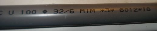
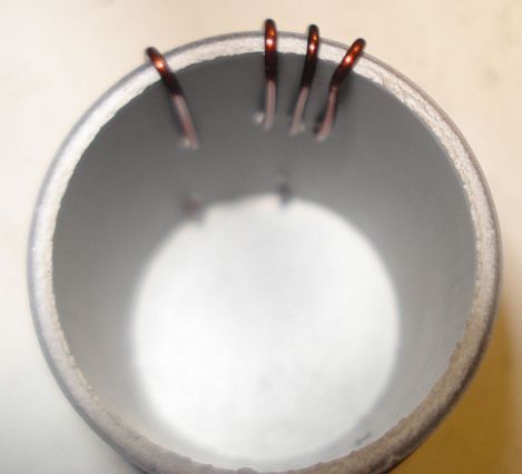
Step 1:
Take a piece of 32mm external diameter PVC pipe from a plumber's shop.
Alternatively, a suitable diameter pills box can be used, or any other
suitable diameter plastic tube.
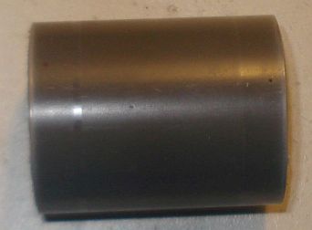
Step 2:
Cut a 4cm piece out of this tube. 4cm is the minimum length required.
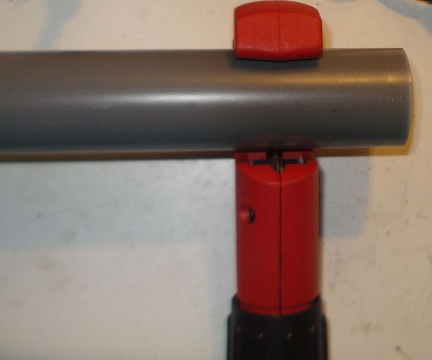
Below a 4cm PVC tube
has been cut in size.
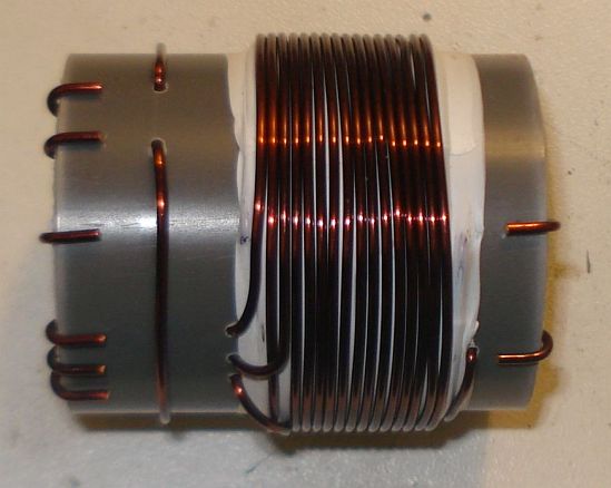
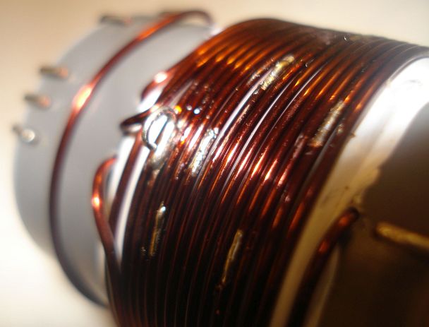
Step 3:
Wind
16 turns of 1mm diameter enameled wire onto the PVC pipe and secure the
winding in place as shown in the picture below. Notice the winding
direction of the wire. This is the primary of the transformer, the one
that is connected to the two capacitors. Notice that this winding is
wound a bit offset to the right of the pipe.
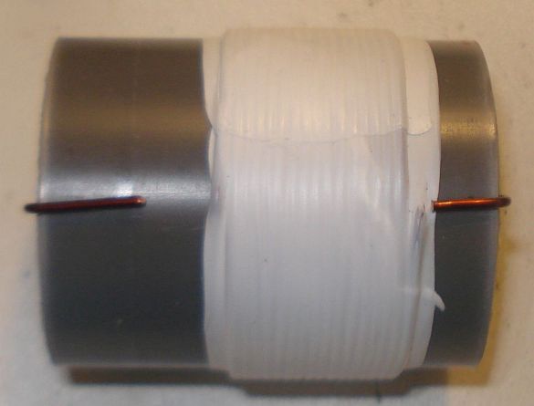
Step 4:
Wrap
the winding with 3 turns of PTFE tape. It can be bought at any
plumber's shop, just like the PVC pipe. The PTFE tape will help in
keeping the second layer turns in place and it will provide extra
insulation.
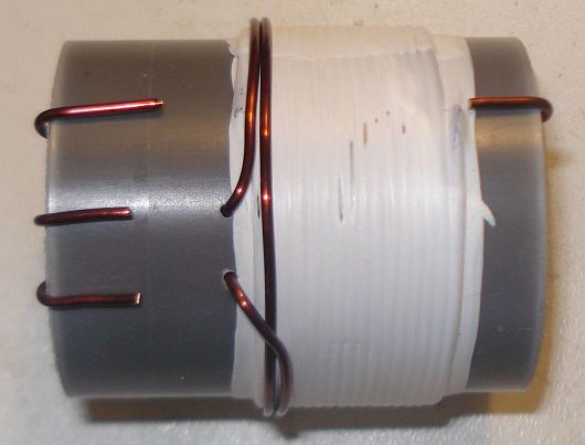
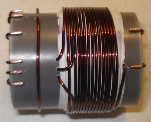
Step 5:
Wind
2 turns of 1mm diameter enameled wire on top of the primary winding and secure the
winding in place as shown in the picture below. Notice the winding
direction of the wire, as well as it's position relative to the primary
winding. This is the feedback
of
the transformer, the one that is connected to the collector of the
transistor.
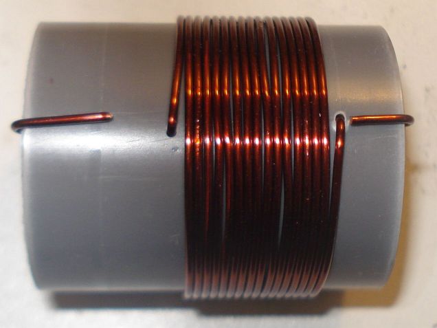
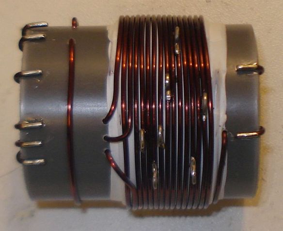
Step 6:
Wind
14 turns of 1mm diameter enameled wire on top of the primary winding,
starting from just next to the 2 turns one and secure this
winding in place as shown in the picture below. Notice the winding
direction of the wire, as well as it's position relative to the primary
and the 2 turns windings. This is the secondary
(output) of
the transformer, the one that is connected to the antenna. At this
point do not worry about the taps yet.
Notice
in the picture below, the way the windings are secured in place onto
the pipe. The wire ends are passed through the pipe using small holes
and then bent towards the ends of the pipe and once more to the surface
of the pipe, where the connections will be made.
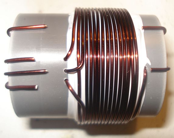
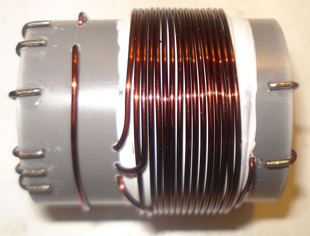
Step 7:
Wind
1 turn of 1mm diameter enameled wire onto the pipe and secure the
winding in place as shown in the picture below. Notice the winding
position relative to the other windings. This
1 turn winding is placed about 1cm away from the other windings. This
is the RF pick up winding, the one that is connected to the
incandescent bulb.
Step 8:
Use
a sharp cutter (knife) and carefully scrap the enamel of all the
windings ends. Do not worry if you cannot scrap the enamel at the
bottom side of the wire ends (that touches to the pipe). We just want
enough copper exposed to make the connection.
Step 9:
Tin
the scrapped wire ends, taking care not to overheat them much.
Step 10:
Now
it's time to make the taps on the secondary winding. Use
a sharp
cutter (knife) and very carefully scrap the enamel of the wire at the
tap points (number of turns).
Take much care not to scrap the enamel of the previous and the next
turn from each tap point. Do not worry if you just scrap the enamel at
the top of the wire (external area). We just want enough copper
exposed to make the connection.
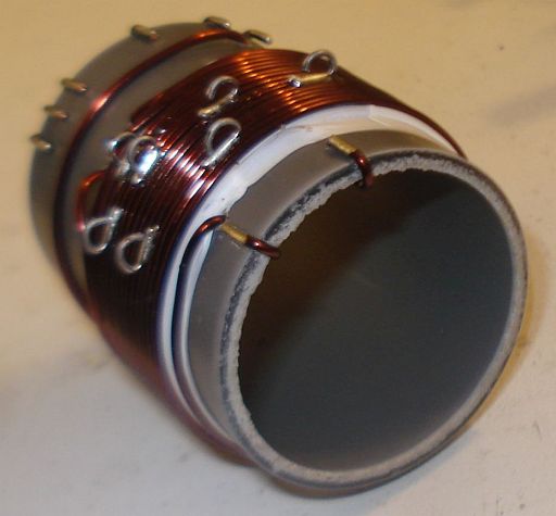
Make
each tap, a bit offset from the near by taps, like shown in the
pictures. This will avoid any short circuits (especially at the 4, 5
and 6 taps) and it will allow for easier connections, especially if
alligator clips are used to connect to the taps.
Step 11:
Tin all the tap points, taking care not to overheat them.
Step 12:
This
step is optional and it depends on how you decide to do the connections
to the taps. You may solder wires directly to the tap points, but in my
case I wanted to use alligator clips, so I did the next: I took a piece
of a component lead and soldered it's one end to each tap point. Then I
bent the component lead to U-shape and cut it accordingly. This created
nice and rigid tap points for the alligator clip.
Step 13:
This
step is optional and it depends on how you decide to mount the
transformer to your enclosure. In my case, I wanted to create three
small legs for the mounting. I cut three pieces of aluminum straps and
made holes at both their ends. I made three small holes onto the
transformer pipe end and mounted the aluminum
straps using screws. After mounting them, I shaped the straps to
L-shape. Then I used
three more screws to mount the transformer to the enclosure.
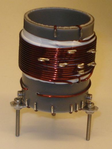
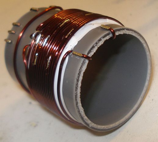
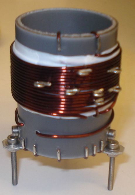
The
completed transformer is shown in the pictures above and below. The 6
connection points at the bottom of the pipe, are the low voltage
points, whereas the 2 points at the top of the pipe, are the high
voltage points.
If you have built the
transformer as described, the bottom connections are as follows (from
left to right):
Wire end 1, connected
to the incandescent bulb
Wire
end
2, connected to the incandescent bulb
Wire
end
3, connected to the VCC (power supply positive voltage)
Wire
end
4, connected to the VCC (power supply
positive voltage)
Wire
end
5, connected to the GND (ground)
Wire
end
6, connected to the transistor collector
The top connections
are as follows (from left to right):
Wire end 1, connected to the
25pF variable capacitor and the 47pF fixed.
Wire
end
2, is the 14th secondary tap and it is left unconnected, or tapped to
the appropriate impedance antenna.
Back to main site