Transformer read only storage (TROS)
A practical guide of how to build your own.

by SV3ORA
Core rope memory
Transformer read only storage (TROS)
A practical guide of how to build your own.
by SV3ORA
This article presents my experiences in designing and implementing a core rope memory. I am implementing a functional 70 bit memory (ten 7 bits words) for demonstration purposes.
Core rope memory is a magnetic read only memory (ROM). Contrary to ordinary coincident-current magnetic core memory, which was used for RAM, the ferrite cores in a core rope are just used as transformers, operating in their ordinary non-saturation region. A pulse from a word line wire passing through a given core, is coupled to the bit line wire and interpreted as a binary "one" while a word line wire that bypasses the core is not coupled to the bit line wire and is read as a "zero".
To implement the ROM, first the suitable toroidal cores were chosen. I have chosen the Amidon FT23-43 cores because of their small size; they are small, but not so small so as to be difficult to wind. Nevertheless, any core could be used, even a non-toroid one, since any core can reassemble a transformer.
The first step in the design, is to measure the voltage that will be induced to the secondary winding, when a pulse comes into the single-turn primary. If the voltage is too low for your application, then you can either increase the voltage of the input pulse, or increase the number of the turns in the secondary winding. I have chosen the second method, so as to make the memory more sensitive to lower voltage input pulses.
After some experimentation, I have found 30 turns for the secondary to be an acceptable number, giving an output pulse of about 15V from an input pulse of roughly 5V. Depending on your application, you may need to change this number to suit your needs. Also, the size of the winding was not too big, so it was practical to wind on these small cores without too much effort.
Testing the transformer requires a pulse generator. Remember,
transformers are AC devices, meaning that they can operate either on
continuous AC or pulse mode, not DC. A quick pulse generator can be
easily made using a 555 timer. Such schematics are readily available on
the internet and in the 555 datasheet. The pulse generator I used, was
connected to the primary of the transformer through a 100nF capacitor,
to cut any DC from passing on to it.
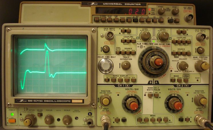
Initial test above, shows the result of a pulse coming into the primary of the transformer. My scope was triggered on the falling edge of the pulse first, so the negative pulse is shown first, instead of the positive. For illustration purposes, the positive pulse will be described first, because in reality the positive pulse occurs first (unless a negative pulse is sent through).
The top trace shows the pulse output from the capacitor of the pulse generator. This pulse is fed into the single-turn primary of the transformer. The bottom trace shows the pulse out of the secondary of the transformer. A rising edge of the input positive pulse (from 0 to 5v), causes a positive pulse on the transformer secondary. Then, as long as the pulse peak stays at 5v on the 555, no DC passes through the capacitor and there is also no AC (or pulse) to pass through it. Thus, no voltage is induced at the transformer secondary. Finally when the falling edge of the pulse comes (from 5v back to 0), it causes a negative pulse on the transformer secondary.
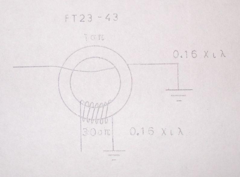
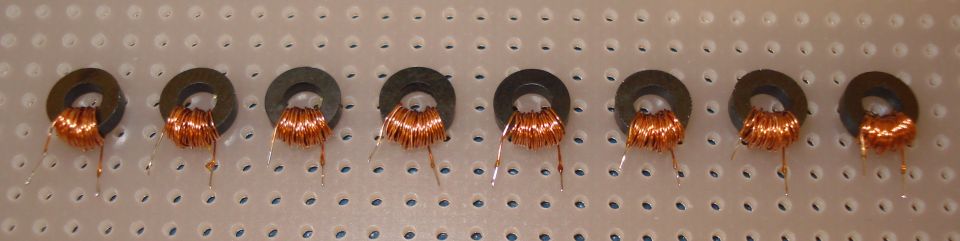
To implement the 7 bit word memory, seven identical transformers are needed. First wind the secondary, which is composed of 30 turns of 0.16mm diameter wire, wound in the direction (polarity or phase) shown in the picture above. The primary is composed of 1 turn of 0.16mm diameter wire, wound in the direction shown in the picture. Do not wind the primary yet, as this will be done during programming of the memory later on. Windings phase is important, so follow the diagram above.
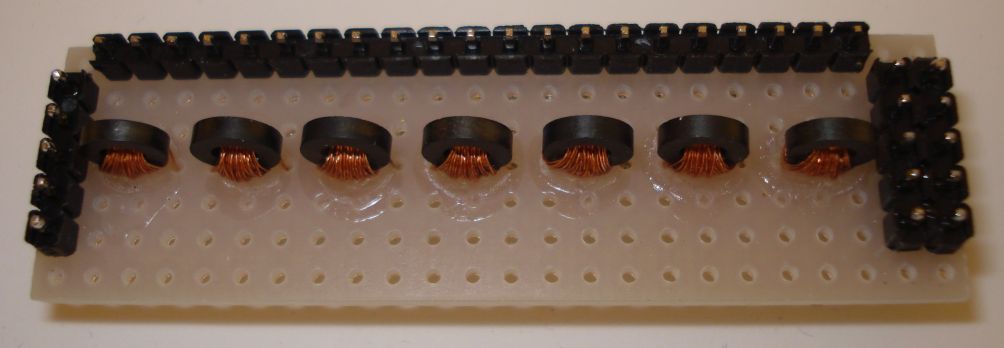
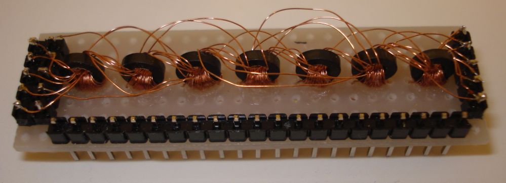
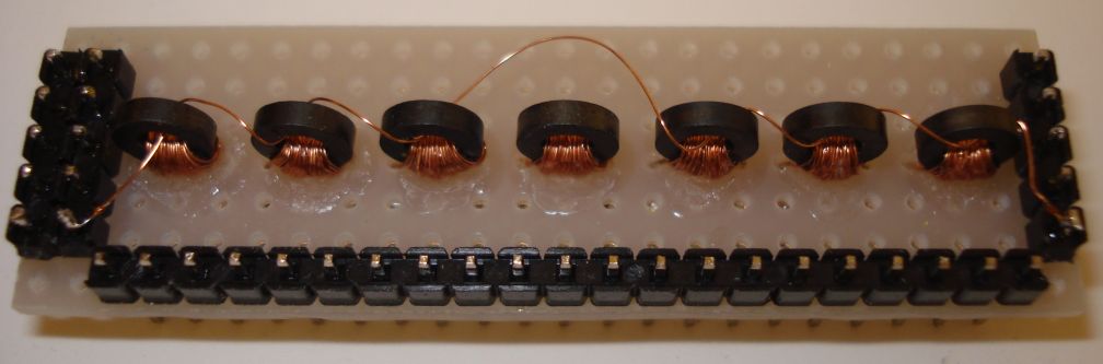
Next, a small piece of proto-board can be used to place the seven transformers, as shown in picture above. The orientation of the transformers was chosen so that coupling between transformers is kept to minimum, in a try to minimize potential noise from unwanted transformer coupling.
The orientation of the transformers can be easily lost when winding the primary and also from vibrations. Thus a small amount of instant glue must be used, to keep them in place. The glue holds the core and the secondary winding firmly onto the PCB.
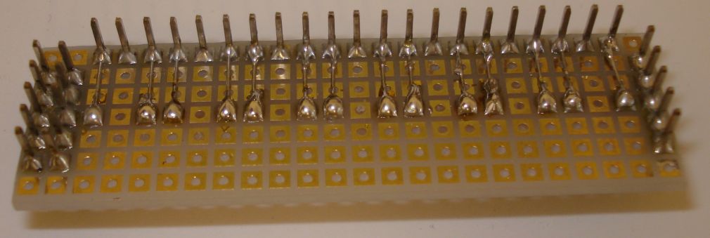
If the memory is to be made modular or used in more than one systems, rows of pins must be used for the I/O connections. These pins allow for easy connection and removal of the ROM from a system, without the need for soldering. Furthermore, these pins must be installed in suitable places, so that extra cabling for interconnections is kept to minimum. A good example is shown above.
Following the prior procedure, a functional non-programmed ROM can be made. Eventually, a program has to be written for it. For demonstration purposes, I wrote a simple program that lights up digits in a seven segment display. First, let's consider a common seven segment display.
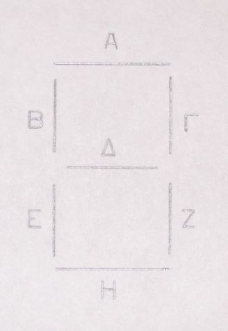
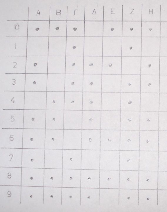
Each row selection of the memory, must light up a specific digit in the seven segment display. Thus, each row must contain the necessary data, so that the appropriate segments of the digit light up. According to the seven segment display above, a table can be drawn so that each memory row contains logic "one" where the segment needs to be on and logic "zero" where the segment needs to be off. In the next table, logic "one" is represented by dots and logic "zero" by the absence of dots.
Now that a simple program is written, it must be "written" in the ROM as well. Writing a program into this kind of ROM, means winding ten wires either through or outside of the appropriate cores. Each time a wire passes through a given core, the output of this specific transformer reads a binary "one", while each time a wire bypasses a given core, the output of this transformer reads a binary "zero".
To better understand how to program the memory, consider the program table as well as the next schematic diagram. To display digit 0 on the seven segment display, all segments, apart from segment Delta (Greek letter), have to be at logic "one". This means that the wire that represents digit zero (which has been chosen to be at "memory address" zero) must pass through all cores, except from the 4th core, that is connected to segment Delta. This is clearly shown in the schematic diagram. Now, you can figure out the rest of the digits connections by yourself.
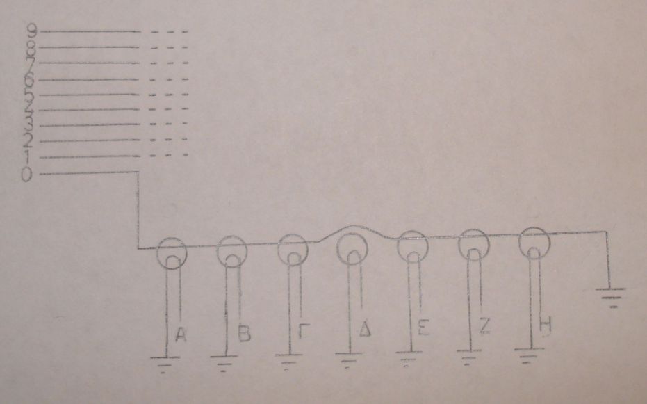
The next picture shows digit 0 (at address zero) programmed into the memory. As explained previously, the wire that represents this digit must pass through all cores, except from the 4th.
Following the same procedure, the rest of the windings must be wound. For the possibility of noise reduction, bypassed wires are brought quite far from the bypassed cores, just to make sure that no unwanted coupling will be made.
Testing the memory requires a pulse generator. Remember, transformers are AC devices, meaning that they can operate either on continuous AC or pulse mode, not DC. A quick pulse generator can be easily made using a 555 timer. Such schematics are readily available on the internet and in the 555 datasheet. The pulse generator I used, was connected to the memory through a 100nF capacitor, to cut any DC from passing on to the memory.
To test the "programmed" memory, a common cathode seven segment display must be connected to it. The appropriate segments anodes must be connected to the appropriate transformers outputs, as indicated in the schematic diagram. Then, connect the pulse generator output to one of the ten memory addresses, that represent one of the ten digits. The appropriate digit should light up. Here is a short video that demonstrates this operation.
As mentioned earlier, the memory works only with pulses, no DC. Thus, for the seven segment display to light up continuously, the pulse generator must continuously generate pulses, so that the appropriate memory address is periodically selected and the appropriate data outputs are periodically set. If your pulse generator frequency is above a few tens of Hz, your eye will see the segments as they were continuously glowing.
More to come...