DDS VFO 0-60MHz
by sv3ora
This circuit has been built and tested by me and it works. To be compact in size and to be able to fit in a handheld device, it uses a mini 1x8 HD44780 compatible display. The datasheet of the display I used is here. The code for the MCU (written by someone else) has been modified to be compatible with the 1x8 display. You can download the HEX file here, and the ASM file here.
Upon boot the message "SV3ORA" is displayed in the LCD. If you want a different message to appear, you have to edit the ASM file and recompile it into a new HEX. When booted, the display shows the frequency in Hz. There are no more digits to display other information and this is the price you pay for the small size. There are three buttons and a mechanical rotary encoder. One button selects between VFO frequency A or B. The other two buttons move the cursor left or right under the digit to which you want to change its value. The rotary encoder is then used to change the value of that digit and hence the frequency of the DDS. When you reach the end (9) of a digit, the left digit to it is them increased by one and the current digit starts from zero again. That way you keep scrolling the encoder, to scan the band of interest in the step that is defined by the selected digit.
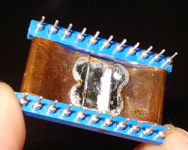
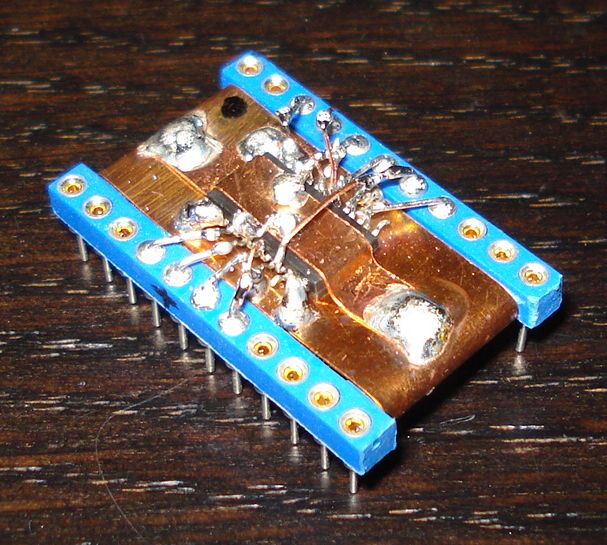
The most
difficult part of a DDS VFO is the soldering of the tiny DDS chip.
There are adaptors to make the job easy, but I did not have any, so I
did some extreme SDM prototyping work onto a larger DIP socket. I used
a copper sheet ground plane folded onto the socket for mechanical
stability. The result is shown in the next pictures.