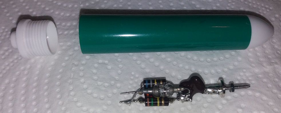
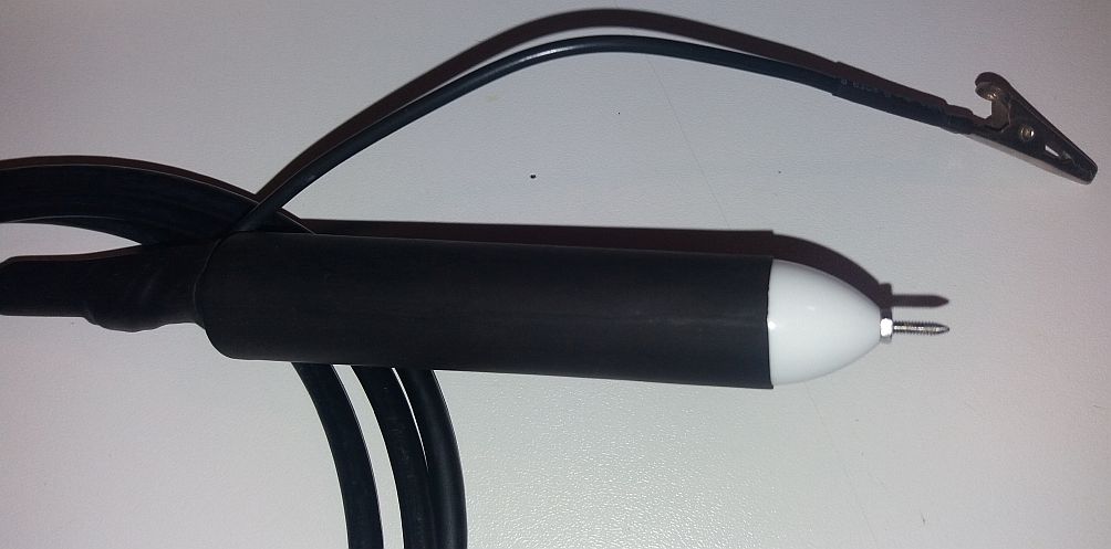
Detector probe
Designed by RCA
High voltage version by sv3ora


Here is my homebrew version of this detector probe a simple but very effective probe that can be used for aligning filters or measuring peak voltages of sinewaves using your oscilloscope and a signal generator or sweeper. The probe is an RCA product and the model is the WG-291. I have modified the probe to work on much higher voltages, yet allow only for one diode voltage drop. The schematic of the original probe is shown below. The only difference from my version, is that I used a 1N58A diode which can withstand 100-120v of reverse peak voltage. The page describes a version with the use of a choke in place or in parallel with R1, but I am only going to use the probe for HF and low modulation frequencies.


The probe has been build using a thick pen for its body and the probe tip is just a stainless screw, made conical at its one end. Because it is a screw, you can easily temporarily attach a small cable/aligator to it, if you want the probe to be held in place (eg clip on a component lead) without holding it. The tip is removable 
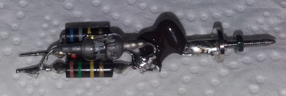
and it is attached to the body using a nut externally and a solderable disc-shaped nut internally. Although no SMD components were used, the components leads were kept reasonably short. A length of cheap RG-58 cable is soldered directly to the probe output connections without any connector, as the cable is part of the circuit. I measured a piece of cable that had a shunt capacitance of 140pF. This cable is taken out of the probe using a hole in the white screw plastic you see in the left of the picture below. The cable is secured firmly in the hole, so that it does not move internally, to prevent damage in the circuit that is soldered to it.


Here is a closer view of the internal components of the probe. The diode used, comes from Amperex. The capacitor is a 1% 500v silver mica type. The resistors are low inductance precision carbon composite 5% which allow for higher voltages. I actually paralleled resistors to get the desired values, first because I did not have the required values available and second because carbon composites have drifted after so many years, so I needed to brind the composite values to ordinary values. I do not think the values are so critical, but I thought to stick to the original design anyway.


The completed probe is shown below. Lots of thermal shrink tube, holds everything together firmly. Note the long ground lead attached to the coaxial braid that comes out of the probe body. I cut a section of the external insulation of the cable and I wrapped the ground lead into it without soldering it. The lead is held in place with thermal shrink tube. No provision is taken in order for the probe to operate on the VHF region. If you want to do so, you need this ground lead to be as short as possible and connect to the ground near the tip. Also, I did not care to shield the probe, as this is a detector probe anyway.


You can use the probe to align IF filters, using the sweeper generator and oscilloscope method. I will not go into details in it, there are already lots of information on the internet. You can also use the probe to measure the output power of your oscillators and transmitters using voltmeters or scopes as display devices. Because I have designed the probe to withstand high input voltages, you should be able to directly probe your 100W HAM radio station (200Vpp at 50 ohms) at the antenna plug without damage the probe. Note that the output of the transmitter must be loaded with a 50 ohm dummy load first! The probe should be able to withstand a maximum of 100v of peak voltage (some other sources say 120v). With this probe, you can make a good use of your old low bandwidth oscilloscope that was sitting in that shelf unsused for years and save some good money from buying expensive spectrum analyzers :)


Back to main site