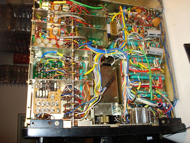
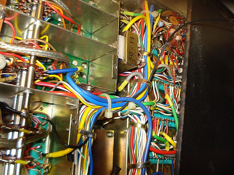
In one of
the "pockets" of the circuits below this lid, you will find the bottom
of the green connector to which the premix unit is connected. We are
interested in the two top pins on this connector, as shown in the
picture below. The top pin is the ground and the pin below it, is the
pin 17 of the premix unit.

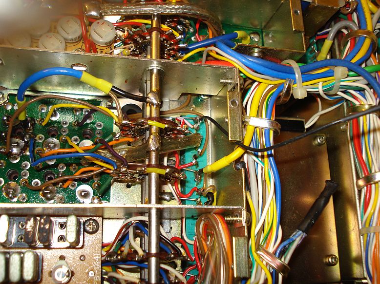
Find a
piece of thin coaxial cable and connect it to these pins on the
connector. How thin? Well, it was to be able to pass through the fin
openings of the bottom cover of the enclosure of the transceiver. If
you haven't got a source for such thin xoaxial cables, note that thin
coaxial cables can be found inside Wi-Fi equipment or old laptops. A
piece about 50cm long or even less, should be enough.
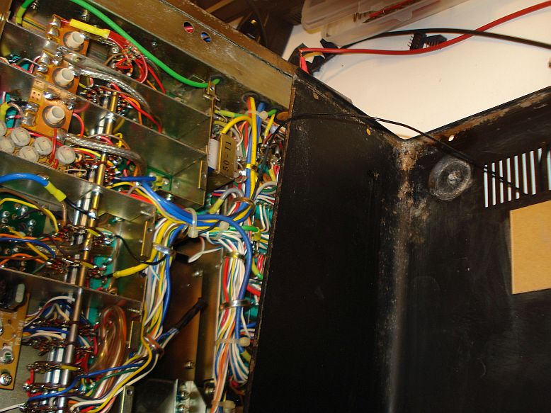
There is a
small opening at the walls of the metal shield, so pass the coaxial
through this opening out of the shield. Then don't forget to screw the
shield back again in it's place.
Use the
clippers that hold the rest of the cabling in place and clip the
coaxial cable along them, just to look pretty. Then bring the bottom
cover of the transceiver close to the circuit and pass the coaxial
cable through it's fins out of the enclosure. I choose the coaxial to
be passed that way out of the enclosure, because I do not want to drill
a hole for the connector at the back of the radio. I simply do not want
to ruin the radio. Any modification should be easily and fully
reversible when needed, to restore the radio in it's original state.