COLLECTED BY
Organization:
Internet Archive
The Internet Archive discovers and captures web pages through many different web crawls.
At any given time several distinct crawls are running, some for months, and some every day or longer.
View the web archive through the
Wayback Machine.
Web wide crawl number 16
The seed list for
Wide00016 was made from the join of the top 1 million domains from CISCO
and the top 1 million domains from Alexa.
TIMESTAMPS
14MHzSSB10mW transceiver
The reason of this events: The reason of this production is very simple.
I wanted to QRV on 14MHz SSB mode. One day when I walking on Akihabara
city in Tokyo , while I have heard the sample transceiver on the ham shop
,I have known that 14MHz can be used for domestic communication. They made
Japanese domestic QSO about 14.18MHz.
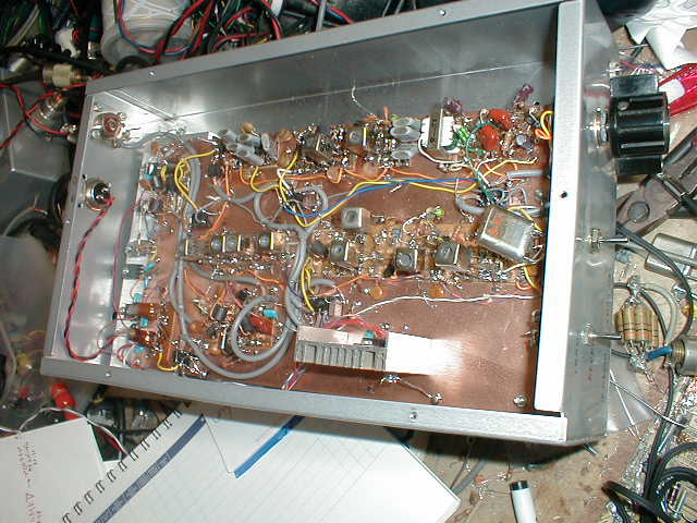
The whole Construction : You can call the transceiver like this as "OZL
type". Characteristics of the "OZL type" are as follows.
1. Single conversion super.
2. Using two DBM-s as modulator and converter.
3. Modulator DBM is used as demodulator in receiving time.
4. All amplifiers are used in transmitting and receiving time.
5. Case is second use of my failed or useless machine.(This time I used
my useless old 10W 7MHz transmitter.)
6. All decals are done with the "Magic ink". Very simple way!
7. Normal "OZL type" uses 12V DC power from cigar lighter of
the car. But in this machine I used 20V DC from my DC power supply. The
reason of my choosing high voltage are as follows. One reason is in order
to press the variable capacitor of the VXO oscillator for it's minimum
capacitance and to get the highest frequency and to get the wide frequency
range of the operation. Second reason is to use 24V relays instead of 12V
relays. I got these 24V relay with only 10 dollar for 10 peace. It was
cheep Junk but super micro molded type can be used for 430MHz. The name
of these relays are G6H2-24V. Maker is OMRON company. Third reason of high
voltage is in order to get 10W power easy with good linearity. In my experience
it is difficult to get 10W with 12V power pupply.
Explanation of the circuit diagram:
1. The black circle marked capacitor is 0.01 micro F ceramic capacitor.
2.You should adjust the snow marked two capacitors on the oscillators to
be got the maximum each output power.
3. All NPN transistors who has no mark are 2SC1815. Maker: Toshiba. Usage
:signal amplifier. Pc=0.4W, Vcbo=60V, Hfe=70 to 700, ft=80MHz.. I show
you the character of another transistors as follows. 2SC1815:maker=Toshiba:usage=amp:Pc=0.4W:Vcbo=60V:Hfe=70to700:ft=80MHzmin///
2SC1740:maker=Rohm:usage=universalamplifier:Pc=0.3W:Vcbo=50V:Hfe=120to820:ft=180MHz///
2SC2491:maker=Sanken:usage=powersalamplifier,switching:Pc=50W:Vcbo=100V:Hfe=unknown:ft=30MHz///
2SC1969:maker=Toshiba:usage=CB bandRFpoweramplifier:Pc=20W:Vcbo=60V:Hfe=unknown:ft=unknown,
(Po=18W,at27MHz,Vcc=12V,Pi=1W)
4. FET used on carrier oscillator is 2SK241. Maker Toshiba. Mos FET. Usage
=FM VHF amplifier. Id=30mA, Pc=200mW, Idss=1.5 to 14mA, gm=10mS, Crs=0.035pF,
PG=28dB on 100MHz.
5. FIve micro relays named "G6H2-24V" are used as switching the
connection of the circuit, from receiving to transmit. This relay is made
by Omuron Co,. in Japan.
6. T1,T2,T4 are FB801 tri -filer 2turn with 0.2mm diameter enamel wire.
7. T3 and T5 are FB801 deca-filer 2 turn. Deca filer means the transformer
made with four wires.
8. T6 is FB801 double filer 2 turn. Double filer means the transformer
made with two wires.
9. Low pass filter are made with the coils "8.0mm diameter bobbin,
0.2mm EW 7 turn." This is designed as a Pie type low path filter with
Q=1 frequency is 14MHz.
Block diagram of trnsmitter
signal flows left to right
dinamic
microphone |
audio
amp |
DBM1
as
modulator |
11.806Mhz
DSB
signal |
crystal
filter makes it
to LSB
|
IF
AMP |
DBM2
as
convertor |
14MHz
USB |
14MHz
BPF |
3stage
HF
AMP |
LPF |
ANT
14MHz
USB
10W |
|
|
upper |
|
|
|
26MHz
go upper |
|
|
|
|
|
|
carrier
oscillater
11.806MHz |
buffer AMP |
|
|
2channel
VXO
13MHz |
pusu-pusu
doubler |
|
|
|
|
|
Signal flow on transmitting time:
1. I use 600 ohms dynamic microphone. It generates 50mVc-p signal with
my voice. This audio A- class amplifier has 30dB voltage gain. Therefore
my voice becomes over1Vc-p signal on it's outside. LED diode clipper is
used to limit the amplitude of the outside of the audio amplifier for 250mVc-p.
LED 's inner impedance become low when its voltage becomes over 2 volts.
Four LED's are connected parallel series. Therefore the amplitude of the
first side of the audio output transformer cannot be 4Vp-p. This audio
signal is used to modulate the carrier in the next stage.
2. Carrier oscillator is constructed with 11.806 named crystal and FET.
It oscillates 11.8072MHz actually. In order to generate the frequency on
the upper slope of the crystal filter , this oscillator shall be tuned
at this frequency. In this case I had to use FET only on this circuit.
With transistor I could not tune the frequency on 11.8072MHz. When I made
D-G pierce oscillator the frequency became higher than 11.808MHz. I changed
the oscillator circuit to G-S pierce circuit. Then it oscillated 11.805
MHz. I changed the two crystals parallel , the frequency became 11.806MHz.
I got 11.8072MHz by connecting three crystals parallel. In order to drive
the double balanced modulator (DBM) as it's requiring local port signal
strength , that is over 1mW, I had to set the buffer amplifier between
the local oscillator and LO port of the DBM. This buffer outputs 2Vc-p
signal. It is enough strength to drive the four diodes of the DBM and not
to be disturbed by the audio signal on RF port of DBM. LO port carrier
signal have to be strong more than 10dB than the modulating signal of RF
port, to ensure the correct action of the modulator. Or else , the modulated
signal becomes " over modulation".
3.Please look another page of my home page about the construction and action
of DBM. Here I used four silicon signal diodes named 1S1588(Toshiba Co,.).
And also I used a pair of ferrite core named FB801, to construct each double
balanced mixers. Here this DBM1 is used as a modulator. Here the 11.8072MHz
CW signal is modulated by the audio signal. On the IF port of this DBM1
happens (comes up) the carrier suppressed double side band signal. You
can see the 56 ohm resister on the IF port of the DBM1. It is used to shorten
the output impedance of this DBM, not to be over 56 ohms. Without this
resistor , the carrier suppression become 20dB worse. With this resister
the carrier suppression are achieved as about -40dB.
4. Because the carrier frequency is located on the upper slope of the pass
band of the crystal filter, only lower side band of the double side band
signal on the IF port of the DBM1 can be pass through crystal filter. Upper
side band signal is rejected to path through the crystal filter.
5. This lower side band signal (LSB) is amplified with the IF amplifier.
The LSB signal came out of this amplifier is 400mVc-p with 50 ohms load.
6. In order to get the wanted 14Mhz USB signal from this 11.8MHz LSB signal,
26MHz CW signal shall be used. The calculation is " 26MhzCW -11.8MHz
LSB=14.2MHzUSB". Please remember that "when the mixer generates
the difference of two input signals, the USB changes LSB, LSB changes USB",
and, " when the mixer generates the sum of the two input signals ,
USB became from USB, LSB became from LSB". I have about 5 kg of crystal
( several hundred). I chose from this stock the crystal named 13.025MHz.
With this crystal VXO ( crystal controlled frequency tunable oscillator)
is constructed. It generates from 13.0119 to 13.0257 MHz. This signal is
doubled with a push - push doubler. The output of this buffer amplifier
is from 26.023 to 26.0514MHz1.5Vc-p CW signal with 50 ohms load. This signal
drives the LO port of the DBM2.With This local signal I can make 14.2166
to 14.2442MHz as it's transmitting frequency. Yes It can be used on the
SSB band. But I want to make about 14.18MHz in order to get many chance
to meet the Japanese domestic stations. Therefore I requested to ham shop
to send me 13.000MHz crystal. With using this crystal, I could oscillate
12.9975 to 13.0043MHz. I can QRV from 14.1878MHz to 14.2014MHz with this
crystal as indicated channel one on the circuit diagram.
7. On the DBM2 , 26MHz CW and 11.8MHz LSB signal is mixed. And the 14.2MHz
USB signal is obtained(got) on the RF port of the DBM2. Here the signal
rebels of the local port and IF port shall be compared. Anytime the LO
port shall be driven stronger then IF port more than 10dB.
8. Already I got 14.2MHz USB signal. This signal is amplified by the Radio
frequency (RF) amplifier unit. The first step of the RF amplifier is made
of A class single amplifier. The second step of the RF amplifier is constructed
by the B- class push- pull amplifier. In order to stabilize the bias of
final amplifier the power diode 10D1 is used with a 30mA of bias current.
Here shall not to be used the small signal silicon diode like 1S1588. Please
remember that " With more current on the bias diode, more stable of
the bias circuit is achieved". T3 is made from four wire transformer.
Instead of T3, two tri- filer transformers can be used. But T3 is more
save resources type. ( But to make such a hand made rig with myself is
not "save resources type action" as itself. Anyway the amateur
radio is the "King's hobby", effective only to spend money and
time)....On the front of the RF AMP unit , the 14MHz band pass filter is
located. This filter reject to income some unwanted signals coming to RF
AMP unit. On the end of the RF AMP unit, 14MHz low pass filter is located.
It prevents to go out the unwanted harmonized signal born in RF AMP unit.
Without this filter , this rig may cause the TVI , we call "I- chen"
in Japanese. This filter is required by the government to allow to use
the rig as a machine of amateur radio.
Block diagram of receiver
signal fows left to right
ANT
14MHZ
USB |
14MHz
BPF |
2stage
HF
amp |
DBM2
as
convertor |
11.806Mhz
DSB
signal |
crystal |
IF
AMP |
DBM1
as de-
modulator |
pri
AMP |
AF
AMP |
head
phone |
|
|
|
26MHz
go uppe |
|
|
|
upper |
|
|
|
|
|
2channel
VXO
|
13MHzpusu-pusu
doubler |
|
|
carrier
oscillater
11.806MHz |
buffer
AMP |
|
|
|
Signal flow of the receiving time:
1. The 14MHz USB signal came from the antenna (aerial) is amplified by
the RF amplifier unit.
2. This 14MHz USB signal and the oscillated 26MHz signal are mixed on DBM2.
It products the 11.8MHz LSB signal. We call such a character of DBM to
send a signal from RF port to IF port and from IF port to RF port as "two
way ability". I feel this ward may be English or German originally.
My translation made from Japanese with my sense. I am afraid to make miss
translation.
3. This 11.807MHz signal is amplified by the IF amplifier. You can see
the collector current is reduced when receiving time. Instead of this method
the IF amplifier makes unwanted self oscillation.
4. Also in this receiving time, 11.8072MHZ carrier drives the LO port of
the DBM1. Therefore the carrier suppressed upper side band signal (USB)
on the IF port of the DBM get the carrier again. It becomes the audio signal
on the IF port of the DBM1. This process is called as the demodulation.
5. This demodulated audio signal is amplified by the audio amplifier. And
it is heard with the head phone. In receiving time pri-audio amplifier
is add to audio power amplifier to get more total gain. And the audio is
heard with head phone.
The result of this transceiver:
I made nine QSOs with this rig and 14MHZ dipole antenna on the berranda
of my house about 10M high. Please look the end of this page ! I made contact
with another aria in Japan from my house located in Tsuchiura city. 14MHz
can be used only from 10 o'clock before noon to two o'clock after noon
for domestic communication. But I feel I would have Yagi antenna!!
14mssb10wfh.jpg
14mssb10w.gif
14MHz 10W SSB Transceiver
製作の理由:今回の製作の理由は極めて単純です。秋葉原のハムショップでアマチュア無線の機械をいじっていて、この14MHzが国際バンドでありながら、お昼前後はどうやら国内のQSOにも使えるらしい事がわかったので、作ってみました。
全体の構成:今回も手慣れた「OZL方式」すなわち、全ての回路を送受信共用で使用して、リレーで切り替える方式をとりました。今回この機械は固定でのみ
使用する前程(移動で14Mのアンテナを上げるのはちょっと大変そう)なので、電源は家(うち)の安定化電源の最大電圧である20Vで設計しました。
20Vと高く設定する事によって、車のシガライターから電源を供給して移動運用できる可能性が無くなるというデメリットがありますが、逆に下記の3つのメ
リッタが得られます。?@外部から供給した20Vを7815で15Vに安定化して作った内部安定電源電圧でバリッキャプの容量最小になるまで、じゅう分に
バリキャップを絞り上げてつかえるので、VXOの可変範囲が広がり、結果としてバンド内でのカバー範囲が広げられる。(後で詳細説明します)?A12Vリ
レーは用途が広いので秋葉原でも1個300円程度するが、ここでは人気が無い分安く、10個1000円で入手できた、G6H2−24Vのストックを使用で
きる。?B電源電圧が高い方が、ファイナルの増幅器の出力電力が出しやすい。他のページでも言ってますが、電源12Vで10W出すのは、結構難しいです。
私
の経験的には、はい。ケースは蓋付きアルミシャーシーですが、いまから10年前に作成した、7MHzSSB送信機の物を、壊して使いました。
回路図の説明:
1. ●の記号のコンデンサーは、0.01μFのセラミックコンデンサー。
2. 二つの発振器の(*)マークの帰還コンデンサーは、発振出力最大となる様に、ぜひこまめに調整して欲しい所。
3.
図の中番号記載無いのNPNトランジスターは、全て2sc1815。主要諸元:メーカー:東芝。汎用小信号増幅用。Pc=0.4W。Vcbo=60V。
Hfe=70〜700。ft=80MHz。他のトランジスターの諸元も下記に示します。
2SC1815:maker=Toshiba:usage=amp:Pc=0.4W:Vcbo=60V:Hfe=70to700:ft=80MHzmin///
2SC1740:maker=Rohm:usage=universalamplifier:Pc=0.3W:Vcbo=50V:Hfe=120to820:ft=180MHz///
2SC2491:maker=Sanken:usage=powersalamplifier,switching:Pc=50W:Vcbo=100V:Hfe=unknown:ft=30MHz///
2SC1969:maker=Toshiba:usage=CB bandRFpoweramplifier:Pc=20W:Vcbo=60V:Hfe=unknown:ft=unknown,
(Po=18W,at27MHz,Vcc=12V,Pi=1W)
4. キャリアー発振器のFETは、2sk241。主要諸元:メーカー:東芝。MOSFET。FM,VHF増幅用。Id=30mA。Pc=200mW。Idss=1.5〜14mA。gm=10mS。Crs=0.035pF。PG=28dB(100MHZ)
5. 送受信切り替えは超小型リレー、オムロン製のG6H2−24V(24ボルト、2回路)を5個使用しています。
6. T1,T2,T4は、FB801に0.2mmエナメルワイアをトリファイラ(3本捩り巻)2t。
7. T3,T5はFB801に0.2mmエナメル線をデカファイラ(4本よじり巻)2t。
8. T6は、FB801に0.2mmエナメルワイアをダブルファイラ(2本よじり巻)2t。
9. ファイナルの後ろのπ型ローパスフィルターのコイルは8.0mm直径のコア入りボビンに0.2mmワイア7t。(π型ローパスフィルターは、Q=1,周波数14MHz,インピーダンス50オームで設計、CQ出版社「トロイダルコア活用百科」を参照)
ブロックダイアグラム
送信時
ダイナ
ミック
マイク→ |
AF
パワー
アンプ→ |
ダイオード
DBM1
変調器 |
11.806
MHz
DSB信号→ |
水晶
フィルターで
LSB信号
になる→ |
中間周波
増幅器→ |
ダイオード
DBM2
周波数
変換機 |
14MHz
ssb信号
→ |
バンドパス
フィルター |
高周波
電力
増幅器で
10Wに |
LPF |
アン
テナ |
|
|
↑ |
|
|
|
↑ |
|
|
|
|
|
|
11.806
MHz
搬送波
発振器 |
緩衝
増幅器 |
|
|
2チャンネル
13MHz
VXO→ |
プッシュ
プッシュ
ダブラー
26MHz |
|
|
|
|
|
送信時の信号の流れ
1.
私は、ダイナミックマイク(インピーダンス600オームのもの)を普段使用しています。これに向かって話すと、私の声は50mVc―p(センターツーピー
ク;尖頭値:以下同様)の電圧信号になります。オーディオアンプはいわゆるA級増幅器で、電圧利得がこれだけで30dBあります。よって、この増幅器の出
力には、音声信号1Vc―p程度が出力されますが、増幅器のトランスの1次側にLEDによる振幅制限が組まれており、音声出力信号は250mVc―pでク
リップ(制限)されます。これは、LEDが順方向電圧2Vを超えたとたんに電流がながれて、光だし、内部抵抗が小さくなるという特性を利用した物です。こ
の、増幅された音声信号は、第一平衡変調機(DBM1)のRFポートに入力されます。
2.
局発ユニットでは、11.806と書いてある水晶を使って11.8071MHzを発振させています。始めここにはFET2SK241のD−Gピアス回路を
つかってみましたが、どうしても周波数が11.808MHz以上になってしまい、クリスタルフイルターの通過帯域上端である11.807MHz近辺に持っ
てくる事ができませんでした。かといって、そのために水晶を注文する訳にはいきません(別に「行きません」という程でもないんですが、できるだけ手持ちの
部品で間に合わせたいのが心情。しかし、逆にいうと、「水晶を注文する事をためらってはいけない。」とも、申し上げたい)。G−Sピアス発振器を使用して
みた所今度は低くなって11.805MHzを発振しました。水晶をパラにつなぐと1KHzずつ発振周波数が高い方に移動するので、3個並列接続した所でな
んとか目標の周波数である、クリスタルフイルターの通過帯域上端11.807MHz近辺に持ってくる事ができました。しかし、なぜかこの発振器の出力は
0.5V程度とDBMを直接駆動するにはやや不足でしたので、緩衝増幅器を1段付けました。G−Sピアス発振器はいつも使っているD−Gピア
ス回路よりも出力電力が小さい傾向にあります。この出力は、11.8072MHz2Vc−p(50オーム負荷)、すなわち40mW=16dBmなので、十
分余裕でシリコン小信号ダイオード(1S1588)で構成されたDBMを駆動できます。また、音声信号のピークは、さきほど説明した様に250mVc―p
に押さえられていますので、局発と音声信号の比率は(2V対250mVで)20dB程度確保されており、DBMとしても飽和による歪みを発生する事無く動
作できます。
3.
回路図でDBM1と描いた平衡変調機に関しては、作り方及び動作特性が私のホームページの別のページに説明してありますので、ご覧ください。ここでは、音
声信号によってキャリアー(搬送波)である11.8072MHzの信号が変調されて、IFポートには、搬送波抑圧両側帯波(はんそうはよくあつりょうそく
たいは:DSB)信号が出てきます。DBM1のIFポートの所にぶらさがっている56オームの抵抗は一種のインピーダンスクランプです。これが無いと、
DBMの出力であるIFポートのインピーダンスが暴れて、正常な動作が出来ずに、搬送波抑圧比が悪化します。具体的に言うと、搬送波抑圧比が20dB程度
になってしまいます。この対策として付けた物です。山村OMが、我々のバイブル「トロコア」の中でおっしゃっている様に、「DBMの正常な動作を保証する
為には、各ポートに6dB程度の抵抗減衰機を取り付ける事が理想的」なのですが、これでは電力の無駄が発生します。必要な所だけに最低限付けるのが現実的
でしょう。
4.
この搬送波抑圧両側帯波(DSB)信号が、次のラダー型5段水晶フイルターを通過する際に、上側帯波(USB)信号は水晶フィルターの通過帯域からはずれ
ているので、通過できません。、一方、下側帯波(LSB)信号は水晶フィルターの通過帯域を通るので、通過できます。結果として下側帯波(LSB)信号だ
けがここから出て来ます。
5. この信号はフィルターでだいぶ減衰しているので、かるく広帯域アンプで1段増幅してやります。この中間周波増幅器の出力は400mVc―pの下側帯波(LSB)信号です。
6.
一方この11.8072MHzのLSB信号を、目的の14MHzのUSB信号にするには、26MHzの発振信号とミキシングしてやる必要があります。
14MHzのSSBは14.100MHzから14.350MHzの250kHzですので(広い!7MHz帯の三倍も在る)、VXOで全てをカバーする事は
可能です。そこで秋葉原に行って、ハムショップで無線機に触って、14MHzのバンドをスイープしてみた所、お昼休み(12時頃)に14.180MHz近
辺で国内のQSOが聞こえました。どうやらこの辺が国内QSOに使われているらしいと踏んで、ここを含む様に計画しました。私は水晶を5kg程度(数百
個)もっていますので、その中から一番近い水晶をえらびだしました。ラベル周波数13.025MHzの水晶でVXO(可変式水晶発振器)を組んで
13.0119から13.0257MHzを発振します。周波数はFMのチューナー用のバリキャップ(可変範囲5から10pF程度)の物(すいません、部品
袋に入れた型番が読めなくなってます)を使用しています。これを次の「プッシュプッシュダブラー」で2倍に逓倍して、この発振段の出力は、26.0238
から26.0514MHzの1.5Vc−p(50オーム負荷で計測)です。これでは、送信周波数は、この26MHz代から中間周波である
11.8072MHzを引いて、14.2166から14.2442MHzと一応バンド無いですが、目標の14.18MHzを含みません。それで通信販売を
調べた所、サトー電気で売っている13.000MHzの水晶を購入して、別チャンネルとして、12.9975から13.0043MHzを発振させ、送信出
力周波数14.1878MHz14.2014MHzを得ました。正直いって、もう少し下まで引っ張って14.18から14.15MHzもカバーしたい所で
すが、、、。
7.
発振ユニットの出力信号(26MHz)と、中間周波信号(11.8MHzLSB)が第二平衡変調回路(DBM2)にて混合されて、求める14MHzの信号
が出てきます。この第二平衡変調回路(DBM2)に於いても、LO信号そのものは10mW以上の電力があり、DBMのダイオードをON−OFFさせうるに
十分な電力であり、また、これに対して変調する側のここではIFポートの信号は、LOポートの信号に対して−10dB以下の強度に押さえられており、ダイ
オードのON−OFFを妨げない事、言い換えるなら「過変調ぎみ」にならない事を確認してください。
8.
さて最後にDBM2の出力である、14MHzのUSB信号を目的の電力まで増幅するのが高周波増幅ユニットの役目です。この高周波増幅ユニットは、1段目
のA級増幅器と、2段目のB級プッシュプル増幅器で構成されています。特に2段目のバイアス回路には、小信号用ダイオードでは無く、電源用ダイオードを用
いて、これに大量のバイアス電流(30mA)を流し込んでバイアスを安定化しています。また、T3は、4本のエナメル線を捩りあわせて1個のコア
(FB801)に2回通したものです。ここは、トリファイラーのコア2個でも構成できますが、1個のコアで済ませて省資源化しています。
9.
この高級波増幅器だけでも500mWの出力電力があり、十分に交信が可能ですが、そうはいっても1W以下の出力で電離層反射通信をするのはやはり相当つら
いものがあります。そこで、もう1段増幅しました。ここに使っている2SC1969という東芝のトランジスターは、10WクラスのHFアンプとしては、い
わゆる定番です。このトランジスターはアキバで1個250円で買えます。できれば5W出力としてQRP運用したかったのですが、たまたま10W出てしまい
ました。そのままとしています。QRPにそれほどこだわって居ません。QRPクラブの面々ごめんなさい。この、終段増幅ユニットの入り口には14MHzの
帯域瀘波器(バンドパスフィルター)が設けられており、不要な信号が高周波増幅ユニットに入ってくるのを防いでいます。また、高周波増幅ユニットの出力側
には14MHzで設計されたローパスフィルターが設けられています。これは、14MHz以下の信号だけを通して、増幅器内部で発生した高調波である
14MHzの2倍の28MHzや4倍の56MHz,等の高調波を減衰させる為の物です。特に14MHzの7倍の高調波は98MHzに成るので、1
チャンネルに妨害、いわゆるTVI、別名「アイチャン」を発生させますので、これを防いで、御近所に迷惑をかけない為の物です。もし、貴方が田舎の一軒家
にすんでいて、TVIは考慮不要であったとしても、これを設けないと、無線機の認可がおりません。
受信時のブロックダイアグラム
アンテナ
から14MHz
信号→ |
バンドパス
フィルター
→ |
高周波
増幅
2段→ |
DBM2
周波数
変換器 |
11.806
MHz
中間周波
信号→ |
水晶フィルター
と中間周波
増幅器→ |
DBM1
復調器 |
プリアンプ
→ |
電力
増幅器
→ |
ヘッドホン |
|
|
|
↑ |
|
|
↑ |
|
|
|
|
|
2チャンネル
13MHz
VXO→ |
プッシュ
プッシュ
ダブラー
26MHz |
|
11.806
MHz
搬送波
発振器 |
緩衝
増幅器 |
|
|
|
受信時の信号の流れ
1. アンテナから入ってきた18MHzのUSB信号は高周波増幅ユニットでそのまま増幅されます。受信時は、ファイナル増幅器は使いません。
2.
この14MHzのUSB信号はDBM2のRFポートに流し込まれていて、一方DBM2のLOポートには26MHzの発振器の信号が加えられていますので、
結果としてDBM2のIFポートには、上記の両信号の差として、11.8MHzのLSB信号が得られます。この様にDBMにはIFポートの入力信号をRF
ポートに変換して出力したり、RFポートの入力信号をIFポートに変換して出力したりする両方の働きがありこれを「双方向性」と呼んでいます。
3.
この11.8MHzのLSB信号は、クリスタルフィルターで近接する不要な信号を取り除かれた後に、中間周波増幅されて、DBM1のIFポートに注力され
ます。受信時に中間周波増幅器が発振ぎみに成る事を防ぐ為に、受信時のみトランジスターのコレクター電流を下げてつかっています。こんな方便はしたくは無
いのですが、ケースに入れてしまってから気がついたので、こんな安易な方法をとらざるを得ませんでした。
4. 一方DBM1のLOポートには、相変わらず11.8072MHzのキャリアー信号が注入されているので、ここではDBM1は復調器として働きます。すなわち、搬送波抑圧下側帯波に搬送波を注入する事によって、音声信号がDBM1のRFポートに出て来ます。
5. この復調された音声信号をオーディオ増幅器で増幅してこれを、ヘッドホンで聞きます。受信時は、低周波増幅1段では利得が不足するので、2段アンプとしています。この辺のやり口は、別のページの50MHzSSBトランシーバーといっしょです。
運用実績
専用のダイポールアンテナをベランダに張って、家(茨城県土浦市)から下記の如く国内カッキョクとQSO出来ました。交信距離は900kmです。国内と
QSO出来るのはお昼正午前後の数時間だけで、海外と交信するには、ダイポールではちょっとつらいですが、バンドは広い分空いていますので、日曜は結構
ゆっくり話ができます。こつこつ楽しんでみたいと思います。(14メガは平均年齢が高すぎてちょっと私みたいな若造は出難いです。実際。はいはい)
| day |
time(JST) |
call sign |
hisRST |
myRST |
his location |
distance(km) |
| 17feb2001 |
1140 |
JR4WRD |
59 |
44 |
Hamada city |
720 |
|
1148 |
JA4JCY |
57 |
42 |
Tokuyama city |
780 |
|
1445 |
KH0/JQ1NGT |
59 |
59 |
|
3000 |
| 19feb2001 |
1910 |
JR8HNT |
57 |
44 |
Sapporo |
760 |
|
1934 |
JM3RUU |
59 |
53 |
Akou gun |
540 |
|
1104 |
JI5TRJ |
59 |
54 |
Kagawa pref |
600 |
|
1117 |
JA5HJ |
59 |
45 |
Kouchi city |
660 |
| 25 feb2001 |
1935 |
JA4BWN |
55 |
55 |
Iwakuni cuty |
720 |
|
0941 |
JA8BOV |
59 |
57 |
Sapporo city |
760 |
back to index
