COLLECTED BY
Organization:
Internet Archive
The Internet Archive discovers and captures web pages through many different web crawls.
At any given time several distinct crawls are running, some for months, and some every day or longer.
View the web archive through the
Wayback Machine.
Wide17 was seeded with the "Total Domains" list of 256,796,456 URLs provided by Domains Index on June 26th, and crawled with max-hops set to "3" and de-duplication set "on".
TIMESTAMPS
2SC1957 linear AMP
The construction of linear amplifier is common interest of our homebrewer.
Because all the SSB transmitter has some kind of the linear amplifier.
I will inform you one type of my product. I used it on my 50MHz ssb transceiver.
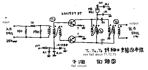
With it I made about 500 QSO's. See fig 1! That is normal wide band push-pull
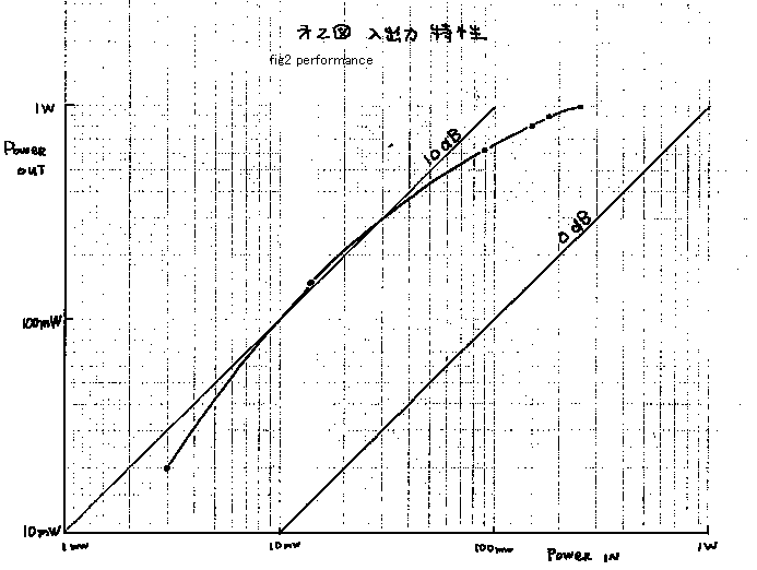
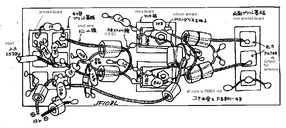
AMP. The performance of it is shown on fig 2. The construction of it is
shown on fig 3. I will describe about some know-how about a linear AMP.
**
1.ATT : To correct an error of impedance match, some kind of attenuator
is need on the input of a AMP. The more attenuate, the more stability.
But,the more attenuate, the more loss of gain. ***
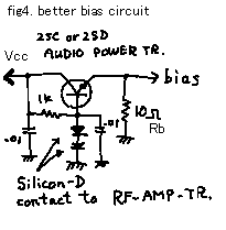
2.BIAS : In fig 1, I used simple bias circuit. But in these days, I like
the better bias circuit(fig4). In this circuit, the smaller Rb, the more
stability. The smaller Rb, the more power-supply-current. ***Discription
add on 4 Dec 2000: Only with diode , you can make good stability if you
choose bias current to make ten times heat lost power may happen on the
diode than the maximum input signal power of the linear amplifier.
3.FT : If you choose the transistor that has more ft, you can get more
gain. If you choose the transistor that has more ft, you can loss more
money. ***
4.RE : The resistor of emitter (=1 ohm) be bigger, the more stabirity.
But then you lost more gain. ***
5.VCC : The more Vcc, it makes the more power.
5.GND : Make wide ground line on the print boad ! We call " BETA-EARTH".
And wire used power line must be thick one.
2SC1957 リニアアンプ
「自作水晶フィルター段数と特性」等といった話題を持ち出しても、同じ自作家でも乗ってくる人と乗って来ない人がいます。しかし、このページに紹介した様な「リニア増幅器の構造」は,我々自作家にとって共通の興味の対象です.なぜなら、すべてのSSB
送信機が,何らかの種類のリニア増幅器を持っているからです.まあ、いわゆる必修科目でしょう。このアンプは、50MHz
SSBトランシーバーに組み込んで使いました.それで,約500局とQSOしました.図1
を見て下さい! それは,普通のワイドバンドプシュプルアンプです.性能は,図2で、構造が図3です。リニアアンプのノウハウについて述べてみます.
1.アッテネーター :
インピーダンスマッチのエラーを正すために,何らかのアッテネーターが,そのアンプの入力部に必要です.よりアッテネータが大きい方が,動作が安定になり
ます.しかし,アッテネータが大きい方が,利得の損失が大きくなります.(記載追加4dec2000:ダイオードだけの簡単なバイアス回路でも、その回路
の入力信号の最大値の10倍程度の電力を常時ダイオードに”損失させてやる”程度に、バイアス電流をながしこんでやれば、安定する様です。)
2.バイアス回路:
図1では、簡単なバイアス回路を使いました.しかし,近頃で,私は,FIG4の様な、よりよいバイアス回路が好きです.この回路では,Rbをより小さくす
ると,より多くの安定が得られます.しかし、Rbを小さくするほど、バイアス回路に対して、多くの供給電流を必要とします.
3.トランジスターの遮断周波数 ft : もしあなたが,より遮断周波数(ft)の高いトランジスターを選べば,,もっと増幅利得を得ることができます。しかし,ftの高いトランジスターを買う為には,より多くのお金を必要とします.
4.安定化抵抗: エミッターの抵抗器( = 1 オーム)を,より大きくすると,より動作が安定します.しかし,その場合、ゲインが落ちてきます.
5.電源電圧:
電源電圧Vccを高くすると,より多くの最大出力が可能になります.同時に増幅率も少し増加します。しかし、多くの高周波トランジスターは12または
13.5ボルトの電源電圧で使用する様に出来ています。むやみに24Vかけたりすると、すぐに壊れてしまいます。秋葉原で安売りされている高周波トランジ
スターの中には、7.3V用の物があります。これは12Vでは、使えません。ご注意!無理しても壊れますHiHi.
6.アース : とにかくリニアアンプには大きな電流が流れるので、アースラインをベタアースにして、ふらつかない様にしなくては成りません。また電源も太い線で配線してください。
c1957-1.gif

c1957-2.gif

c1957-3.gif

c1957-4.gif

back to index


