COLLECTED BY
Organization:
Internet Archive
The Internet Archive discovers and captures web pages through many different web crawls.
At any given time several distinct crawls are running, some for months, and some every day or longer.
View the web archive through the
Wayback Machine.
Web wide crawl number 16
The seed list for
Wide00016 was made from the join of the top 1 million domains from CISCO
and the top 1 million domains from Alexa.
TIMESTAMPS
50.25MHz am simple transceiver----5025amph.gif
 Simple
and useful! 50MHz AM QRP transceiver *
On the book of "6m Handbook" in Japan, I informed about my project
of 6M AM transceiver. That is real OZL style project. It uses many new
strange idea. It uses double baransed mixer for AM modulation. But....
One day , when I talked with an OM on the air, we agreed that "AM
transmitter must be made by final modulator!". Therefore I made this
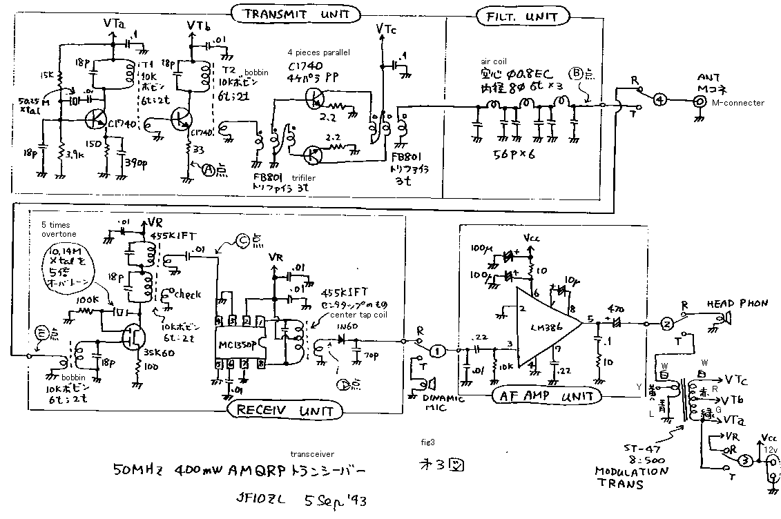
transceiver. See the figures! Fig1 and 2 are block diagram. Fig3 is circuit.
*
I will explain about a transmitter. The crystal oscillator makes 50.25MHz
signal. Driver and final amplifies this signal for 400mW power. If you
cut (A) point and make keying , it becomes a CW transmitter. If you makes
CW transmitter , joint a dummy load on (B) point! Tune a core of T1 and
T2! If you have a receiver , you will be able to receive a strong signal
on 50.25MHz. *
If you construct a CW transmitter , make a modulator and modulate a CW
signal! A modulator is a type of an audio amplifier. It is made by LM386
audio AMP. If you make it , please test it like fig4! Pour an audio signal
on the microphone terminal! Connect 8 ohms of a dummy load on the output
terminal! If you do not have a signal generator, make a test like fig5!
*
On the point of VTc , there appears a signal like fig6. This is a signal
12V DC with audio signal. If you use this voltage for the power supply
of the CW transmitter, you can obtain a modulated signal. I tried to modulate
only with final, the modulated signal has a distortion indicated like fig7.
If you have an oscilloscope, please make the same experiment! *
The receiver is a single super heterodyne. 3SK60 constructs a self oscillating
convertor. MC1350 constructs a IF amplifier. LM386 constructs an audio
amplifier. The total gain of this receiver is 115dB. If you make IF AMP,
please check it. Pour a 450kHz signal on the (C) point! Measure the signal
come out on (D) point! Tune the core of the coil! Test this whole receiver
like fig8! If you can receive a signal unless connecting the signal generator
and receiver, it is OK. *
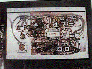
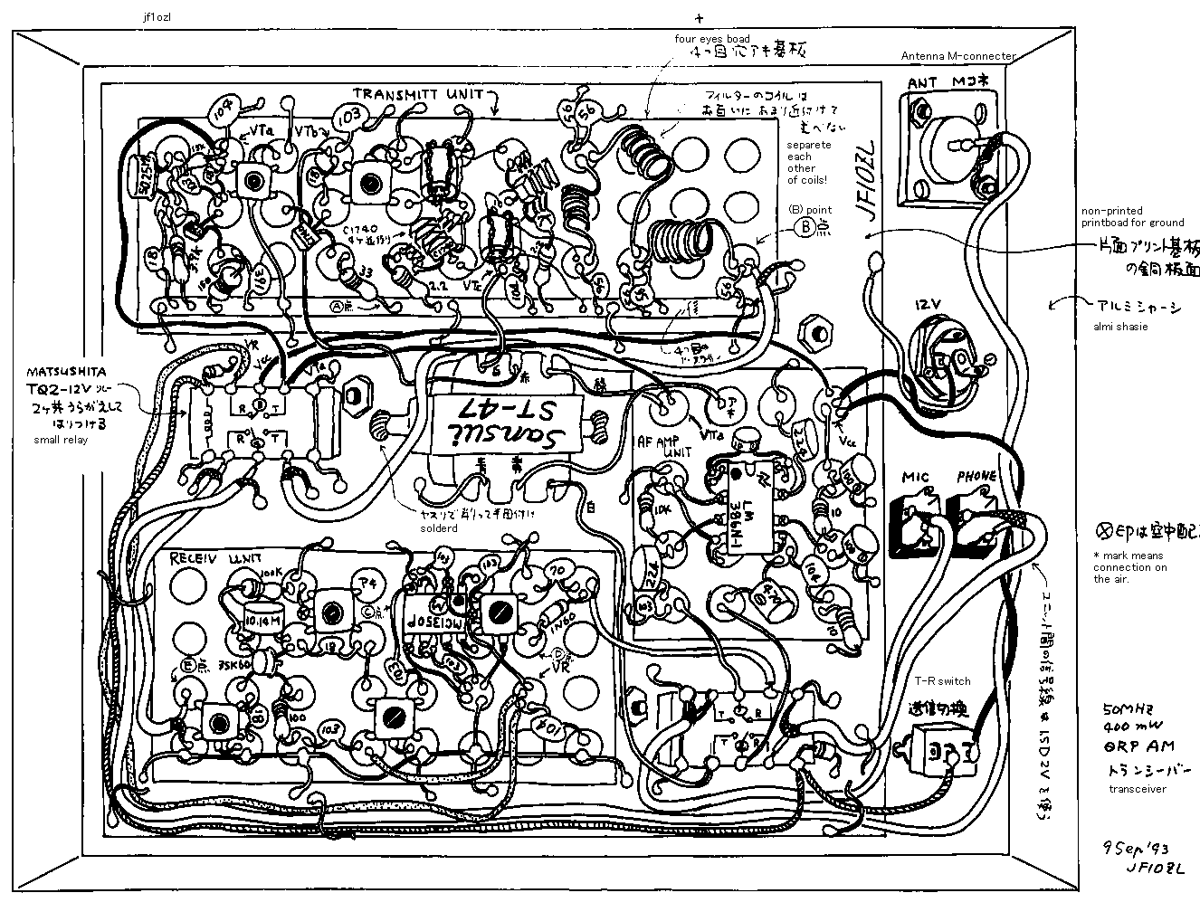
Connect the each circuit with a small relay and coaxial wires! Make case
! *
I used this transceiver on the hill for 2 hours. I made contact with 19
stations. Most far of them was 200km distances. In Japan AM can be used
only 50MHz in these days. I do not know the circumstances on another countries.
作り易くて実用的な、50MHzAMQRPトランシーバー*
あるOMさんと、お空で話していて、「やっぱりAMは強電力変調だ!」という無根拠な合意に達してしまい、作ったのがこのトランシーバーです。ブロックを図1、2。回路図を図3に示します。*
まず、送信ブロックを作ります。オッシレーターで水晶発信器により、50.25MHzを発振します。これを、ドライバーとファイナルの2段で増幅して、送
信出力400mWを得ます。ここまでの回路だけでも、例えば、ドライバーのエミッター{(A)点}をキーイングすれば、立派なCW送信機の出来上がりで
す。送信ブロックが出来たら、(B)点にダミーロードを付けて、出力が最大になる様にT1とT2のコアを調整してください。50MHzの受信機があれば、
強力な信号が受信できるはずです。*
さて、CW送信機ができたら、これに変調をかけて、AM送信機にします。変調器は低周波パワーアンプなので、LM386を使いました。このユニットも単独
で、図4の様に、入力に低周波シグナルジェネレーターの信号をいれて、出力に8オームのダミーロードをつないで、500mWの出力が出る事を確認しておき
ます。でなければ、図5の様に簡易的にでも確認しましょう。*
VTcには図6の様に、12Vの直流にマイクからの信号が重なって、出てきますので、これを、先ほど作った高周波送信機の電源として加える事によって、
50MHzの信号が振幅変調されて出てきます。昔から、トランジスター送信機においては、ドライバーにも軽く変調をかける事が推奨されてきました。私も、
ためしに、1kHZの正弦波をかけて、ファイナルのみに変調をかけてみた所、図7の様に歪みがでました。オッシロスコープをお持ちの方はぜひやってみてく
ださい。*
受信部は、シングルスーパーです。3SK50による自励式コンバーターと、MC1350Pによる、IFアンプにより70dBを得て、LM380によって電
力増幅し、総合利得は115dBです。IFユニットを作ったら、入力(C)点に450kHZの信号を入れて、(D)点に増幅されて出てくる事を確認してく
ださい。うまく動作する様に各コイルのコアを調整します。受信機全体のチェックは、図8の様にしました。机の上にシグナルジェネレーターを置いて、受信ユ
ニットと低周波ユニットを動作させておいて、シグナルジェネレーターと受信ユニットは電線でつながないでも受信ができれば合格です。*
ここまで出来れば、後は、送受信切り替えリレーを配線して、ケースにいれます。**
本機を持って、近くの峠(茨城県新治郡新治村:朝日峠300mH)で移動運用して、CQを出した所、三郷市、川崎市、大和市、沼津市等と2時間で19局と
の交信が出来ました。本当に簡単な割には、実用性は十分です。運用してみて判ったのですが、イメージ周波数が51.15MHzのFMに成るので、FMの混
信を若干受けます。また、クリスタルフィルターが無いので、強力なSSBの混信もありますが、感度そのものは十分でした。AMは、50.50から
50.60MHzで運用される事が多いのですが、よっぽど混んでいる時期でなければ、かえって50.25から50.30近辺でCQを出したほうが応答があ
ります。多少勇気がいりますが、10年ほど前はこの辺で移動局がAM,SSB,CWを同じ周波数で運用していた物です。遠慮せずにCQを出して見ましょ
う。自作のAMで出ると、「待ってました」とばかりに、自作局が応答してくれます。
50.25amfig.gif

50.25cir.gif

50.25amjittai.gif

back to index

 Simple
and useful! 50MHz AM QRP transceiver *

