COLLECTED BY
Organization:
Internet Archive
The Internet Archive discovers and captures web pages through many different web crawls.
At any given time several distinct crawls are running, some for months, and some every day or longer.
View the web archive through the
Wayback Machine.
Wide17 was seeded with the "Total Domains" list of 256,796,456 URLs provided by Domains Index on June 26th, and crawled with max-hops set to "3" and de-duplication set "on".
TIMESTAMPS
50MHzAM40mW Handy transceiver
I wanted to use a pair of handy transceiver to use holiday. AM is good
mode to use such a purpose because I am an OM. Therefore mode was decided
as AM. I decided to make it with a single conversion. Therefore I need
a crystal that can oscillate a transmitting frequency directly. On the
catalogue of the parts shop I could find 50.55MHz. Transmitting frequency
was decided such a way. I want to use a 455kHz IFT for the IF transformer.
On the catalogue of the parts shop I could find 50.10MHz. 455kHz IFT must
be able to tune for 450kHz. I wanted to make this transceivers with the
" surface mount construction" ( You will use another word for
the same meaning. It is not English but Japanese, HiHi. ) But in Japan
on the summer of 2000 , we can not buy the parts for surface mount construction
even on the AKIHABARA city. Therefore I decided to make this (these) with
conventional configuration. Rear side is print pattern drown by writing
brush. Upper side (parts side) is all ground pattern. Case is lunch box
sold by 288 Yens. I used 5cm square shape 3mm thick 8 ohms speaker. I feel
you can use more normal 8cm dynamic speaker, if you have more space. I
did 200m distance QSO with a pare of these same units. I show you the print
pattern. But you must re draw it in order to match your parts. Please not
to send me the E mail that " Send me the parts match for your project!".
I am not parts dealer. But I will send you this transceiver itself if can
use my gears to educate boys and girls.
Description add on 30Aug2000: As you can understand all this gear depends
on the technique about 20 years ago. You can find the similar projection
on the book about 20 years ago. I tried to make more modern construction.
I will explain about my trial.
1. " Small thin speaker
has poor efficiency." We can get 4mm thick speaker on the
Akihabara electric shop in Japan. But such speakers has 70dB efficiency
to produce the sound from the electric power. How to measure the efficiancy
of the speaker isdecided in the Japanese industrial standard"JIS".
70dB efficiency is 10dB worse than the normal small 5cm speaker used on
the pocket radio. I changed the speaker from 5cm diameter 4mm thick type
to 6.6cm normal dynamic type. I can operate very easily with it with better
feeling. Therefore I think I had better to make speaker hole on the print
board to use conventional type speaker with more better space efficiency.
2. "Space efficiency will achieve over 50% except
by using special order parts and special order made case."
In order to reduce the capacity of the case with the same circuits, we
must use special parts as special antenna connector, special power switch,
special transmitting switch. And we must make the case with ourselves to
make it as just size.
3. " Special parts reduces the re productivity
of listener." I want to use more small push switch for
transmitting switch. I searched (looked for) it in the electric shops.
But I could not find it. Push switch is decided its size in Japanese industrial
standard. Therefore I can not find any other size of them. On the other
hand I could find many size of speakers. In Japan speakers are classified
with its diametric size. But I can find many types of 5cm speakers which
has many size of its driving magnet. If I make the case and print board
to just to my speaker , you will be not able to use it.
4."Mix mount technology looks no good."
I can find some type of surface mount type (chip: I like Chips like as
star treck) capacitors in the shop. But 15pico farads can not be found.
I must use conventional type capacitor for 15pico farads . I could find
many surface mount resisters. But I could not find 0.5 ohms. I could find
the 47micro farads surface chemical capacitor. But I could not find 100
micro farads. I will not get good looks for such a print board that has
many types of parts on the both side. """This page will
be continued!!!!!
Description add on 2 Sep 2000: Once time I made a pair of transceiver with
plastic (poliethiren) lunch box. But it is not see through. I want to show
a printed board in the case to my friends on my local meeting. Therefore
I tried to make a case with clear plastic plate. Once , the plate has broken
when I made a hole on it. My friend Mr.Usui JJ1ILR tought me a hint that
, " Make small hole once ! Use thick drill one by one!" Using
this method, I completed the new case. I want to teach you some another
know how to make case with achril plastic ( sorry my dictionary do not
know the spell of it).
1. How to make a hole.
1-1. If you want to make a hole more than 2.5mm diameter , make 2.5mm hole
once! After that you can make wider the hole with using 0.5mm thicker (fat)
drill.
1-2. Use a drill for iron! Not use a drill for wood!
1-3. The maximum diameter of the hole made by drill is 5.0mm. If you want
to make bigger hole, you should use rasp or sand paper. (( My family name
"SUNAMURA" means " Sand Village" ))
1-4. Lay wooden plate directly under position of the drill anytime! On
the timing of the drill go through the plastic plate, the big shock happens.
This shock is a main reason to break the plate. In order to avoid this
shock, lay wooden plate directly under position of the drill anytime!
2. How to bend an achril plastic plate.
2-1. Buy about 16mm diameter iron bar! Heat it with gas cooking range!
2-2. Wait until 2 "minuten"! Extinguish the fire! Put the plastic
plate on the bar! Wait 10 seconds! Bend the plate be 90 degree !
2-3. Cool down with water while put it on the edge of 90 degree edge of
wodden bar.
2-4. Diameter of inner side after bending is same as the diameter of before
bending. Diameter of outer side after bending is bigger than the diameter
of before bending. When you bend the plate, the outer side of the plate
is extended.
2-5. Anyway try to bend your small useless plastic plate! Make sure about
the diameter and radios after bend with yourself!
3.Annex
3-1. We can not get a screw with our wanted size. In Japanese " Sunday
constructor shop" , we can get 5mm pitch screws. The word "Sunday
constructor" means the man who make construction only in Sunday. On
another days he will works as a secretary or post man or some any another
kind of job. " Sunday constructor shop"is called also as "Do
it yourself shop" in Japan.
3-2. Be care! The length of the bolt may not means the length of the screw.
It may indicates the whole length. The screw I got "M3*35mm"
has only 33mm of its screw length. ( I can use the EMCO multi purpose small
machine , on my fathers house. It can be used as a grinder. If you have
a grinder ,you can adjust the length of the bolt as you like.
Description add on 16 Sep 2000: In this week, I made a new transceiver
with a chip parts. It is smaller than old two models. I decided to call
the new one as a third version. I will talk you what I felt while I make
this third version.
1." With chip parts and order made case , the capacity
of the hole assembly can be reduced for half of the discreet and sold lunch
box." The first version was made of discreet parts and
sold lunch box. It used the 6.6 cm dynamic speaker. The size of the case
was , 140(width)* 95(length)*45(thick). The capacity of it was 600cm2.
The second version was made of discreet parts and plastic (achril) designed
case. It used the 5.0 cm diameter 4mm thick super thin type speaker. The
size of the case was , 130(width)* 85(length)*32(thick). The capacity of
it was 350cm2. The third version was made of chip and discreet parts and
designed case. It used the 6.6 cm dynamic speaker. The size of the case
was , 120(width)* 75(length)*30(thick). The capacity of it was 270cm2.
The second version uses a special speaker. The third version has half capacity
of the first version.
2. " AGC (automatic gain control system) is effective."
I made the third version out of (less) an AGC system. I made QSO with the
third version and the first version. When I made QSO with the distance
over 50m, the two assembly act the same performances. But when I made QSO
with in my house with the different room, the first version can generate
the voice sound as a understandable voice. But then, the third version
generates only loudly rough un-understandable sound. I checked the AGC
voltage of the first version. Vagc of no signal is 0V. Vagc of 1m distance
is -0.73V. Vagc of 5m distance is -0.30V. Vagc of 10m distance is -0.20V.
Original self bias voltage of the RF amplifier FET is -0.57V. Yes, on the
house, the double bias voltage drives the amplifier than the far away.
Sorry I can not calculate the correct decibels. I can say that the AGC
extends the cover aria of the transceiver for nearer side than that of
AGC less.
3." FET can be used as up side down."
Look the figure 3-5! I wanted to use the FET with the opposite direction
of its drain and souse for better design of print board. I used it up side
down. But then leg of the FET becomes far from the print board. It is difficult
to solder it. I bend the leg (lead) of the FET. Care not to break the leg!
If you are professional, you do not use such a way. This method can be
used only by amateur radio hand maker.
4."Chip parts can be got on the SUZUSYO shop in
AKIHABARA city." I walked and looked for the chip parts
on AKIHABARA city for three hours. Only in the SUZUSYO shop ,I could get
the chip FET and chip transistors. In third version I used 2sk210 and 2sc2713
instead of 2sk241 and 2sc1906. Chip resisters and chip capacitors are got
from the junk (broken) print board of some (unknown) digital systems.
5."FET must be lain on the bottom of the coil case."
Look figure 3-1! Even if you use the chip parts, you can not save so many
size. You can save the size ,if you put the FET chip on the bottom of the
coil case, like fig 3-2. In order to put the FET on the bottom of it, the
coil must be 10mm square size. We can get 7mm *7mm coil. But it is too
small, is not it?
6." Use turtle washer to fix the speaker!"
The washer made and sold to fix the waving board of the construction material
is called an turtle washer in Japan. It may not be English. Hi Hi. Look
the figure 3-3!
7."A 1.5mm thick plastic board is enough to use
as a case." On the first version I used 2mm thick board.
On the third version I used the 1.5mm board. 1.5mm is easy to bend. Enough
hardness.
8."Use 45mm diameter whetstone with hand drill
to shorten the screw! ": You can fix a vice (vise) on the
desk. You can fix the hand drill on the vice. You can fix the 45mm diameter
whetstone on the chuck of the hand drill. Make your daughter to drive the
hand drill! You can put the screw on the whetstone. You will need 10 minutes
to reduce the length for 2mm of M3 screw.
9."About next trial". In order
to make smaller transceiver than third version, I must get a technology
of photograph print pattern. In order to look for small sized good speaker
I must make the speaker evaluating system. These new technologies are hard
to get. I decided to stop this project by myself now.
2sk241. Maker =Toshiba, Usage = FM/VHF RF, Type =Mos, N channel, Vmax =20V,
Idss=1.5mA,
gm=10mS,Crs=0.035pF,PG=28dBtyp at 100MHz.......
2sk210. Maker =Toshiba, Usage = VHF RF, Type =J, N channel, Vmax =18V,
Idss=1.0mA,
gm=7mS,Crs=0.65pF,PG=24dBtyp at 100MHz.....
2sc1906,Maker= Hitachi, Usage = VHF A/MIX/OSC, type=NPN, Vmax =30V, Pcmax=300mW,
hfe=from 40to250,ft=600Hz,Cob=2pF,PG=18dB at 200MHz......
2sc2713,Maker= Toshiba, Usage = LF LN A, type=NPN, Vmax =120V, Pcmax=150mW,
hfe=from 200 to 700,ft=100Hz,Cob=3pF,PG=10dB at 1KHz
50m40mw2.bmp
50m40mw3.bmp.....Drowing of print pattern. I drew it with 2/1 size.:::::1、2号機の基板設計図(作図は2/1倍)
50m40mw4.bmp: I like to play with PLAYSTATION........Print pattern of Version
1 and 2.....1、2号機の基板(共通)
50m40mw5.bmp....hand made transceiver with 2 dollers of Tapperware....Version1::::1号機
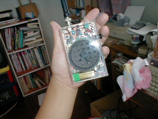
50mh40mwph113.gif....hand made transceiver with my hand made plastic case....Version2::::2号機
50m40mwph3gou.jpg.......Version3:::::3号機
50m40mw3gouex.gif......explanation how to make version3 ....3号機製作に関する説明図面
50MHzAM40mWハンディートランシーバー;21Aug2000
近距離の連絡用にトランシーバーがほしくなり、作ってみました。以前も、50MHzSSBのハンディーをつくりましたが、SSBは、QRHに対応して周波
数を微調整しなければならないので、近距離連絡用としてはむいていない事がわかっています。そこでモードはAMにしました。周波数は、サトー電気の通信販
売で入手できる周波数という事で、ほとんど考慮の余地がなく50.55MHz送信、50.100MHz受信、中間周波は450kHZ(455kHzの中波
用IFTでカバー)ときまってしまいました。ダブルスーパーやプリミックスならいろいろ考えられましたでしょうが、ハンディーですので、シングルスーパー
としました。面実装をやって小さく作ってみようとも考えましたが、面実装のICは我々アマチュアの入手できる範囲ではまだ種類がすくなく、適当なICがみ
つからなかったのと、せっかくICを面実装にしてもIFTが面実装でないので、あまり小さくならなそうでしたので、コンベンショナルにしました。ただし、
今回はできるだけ基板上のジャンパー線をなくしてすっきりまとめようと思いました。写真でおわかりの様に、裏面にパターン、表面(部品面)はベタ
アースとして動作の安定を図っています。(というか両面にパターンを作成するのはちょっと大変ですから。HIHI。)回路は、個人的にも極めて実績の在る
回路の寄せ集めです。受信は、高周波1段増幅付きのシングルスーパーです。中間周波はモトローラーの中間周波増幅専用ICであるMC1350pを使用して
います。低周波増幅はLM386を使って利得を60dB(今回の調整後の実測地)得るもので、私の他のページに詳しく説明してあります。送信は3段の強電
力変調で、変調増幅器は受信用の低周波増幅器と共用です。ケースは実験用の仮のケースで、一個288円のおかず入れです(後でこれを1号機と命名)。これ
でだいたい200mくらいの見通しの交信ができました。スピーカーは5cm角型で厚さ3mmの厚さの超うす型ですが、ケースに余裕があるなら、あまり無理
せず、普通の8cmや10cmスピーカーのほうがずっと効率が良くよろしいとおもいます。いちおうプリントパターンを示しておきましたが、部品にあわせて
御自分でひきなおしてください。私は、トレーシングペーパーの方眼紙に2倍で表面から描いて、裏返しにして50%縮小コピーをとって、それを基板に
乗せて上から「千枚通し」でつついてへこみをつけて、このへこみを頼りに、パターンを手書きしました。パターンを書くには絵筆にマジックインキの補充液を
着けて書きました。
追加記載28Aug2000:この製作が一応完成した後ですが、以上の製作があまりにも20年前の雑誌の製作記事と同じで面白く無い事もあり、もう少し考えたりやってみたりしました。それについてお話します。
1.「小さなスピーカーほど効率が悪い。」昔の丸い頭のスピーカを、基板の中に穴を開けてもぐりこませる業(わざ)は今でも有効。」:どう
もトランシーバーの感度が悪いので、厚さ3mmの超薄型スピーカーを、普通の円筒形の頭の5cmスピーカーに換えてみたらずいぶんと感度が上がりました。
昨日(28Aug2000)アキバで物色していたら、在るお店の3mm厚さスピーカーの正札に70dBと性能記載がありました。70dBといえば、車載の
10cmスピーカーの90dB,ラジオ用5cmスピーカーの80dBと比べて、相当に効率が悪い。車載の10cmスピーカーはハンディーには使えませんか
らそれと比べてみてもしょうがないとして、ラジオ用5cmスピーカーの80dBと比べてさらに10dB悪い。さらに、電気を音に換える効率だけでなく、音
を電気に換える効率も悪そうです。そういった訳で、ハンディートランシーバーにも出来るだけ大きなスピーカーを使うのが良さそうです。そのために、ポケッ
トラジオ等で、昔からやられている様に、基板に穴を開けて、そこにスピーカーを潜り込ませるレイアウトは、性能を確保しながら、全体の大きさをおさえるの
に極めて
有効な事が判明しました。
2.「汎用のデザインでは容積効率50%を超えない」:ここでは、プロが専用の基板とケースを設計して、詰め込んだ場合を100%の効率と
定義しましょう。それに対して、我々が、どんなケースでも入れられる様に、真四角な基板を製作して、その後で何らかのケースを探して製作した場合、なかな
か縦横比や厚みにぴったりの物が無く、最低でもプロの設計の2倍の容積が必要です。自分でケースを板切れから作るのもやってみるとなかなか大変です。
3.「専用のデザインでは、部品の入手性が悪い。」フジヤマプロジェクトでも話題になってましたが、配線の簡素化の為に直付けコネクター等
の特殊部品を使用すると、どんどん部品の入手性が悪くなって、再現性が落ちます。日本では4回路のプッシュスイッチの大きさはどうやら決まっている様で、
きっとJISででも決められているのでしょう。それは入手性には問題が無いのですが、逆にアキバじゅう歩いても、それよりも小さな4回路プッシュスイッチ
は見つかりません。逆に、小型スピーカーの形状、すなわちコーン径に対する頭の大きさや全体の厚さ等の形状は、バラバラで、標準という物が無いようです。
ちょっと不便に感じました。
4.「混載は見てくれが悪い。」先にも述べましたが、現在われわれアマチュアはすべての部品を面実装ではそろえられません。そこで、基板の
小型化を図る場合、いきおい混載すなわち、面実装部品と足の生えた従来部品の両方を使った形式とならざるをえません。そうすると、表面には、DIPICや
FET、IFT、トロイダルコイル、水晶といった部品が並び、裏面には面付けのトランジスター、抵抗、コンデンサーが付く事になります。それだけならいい
のですが、コンデンサーでも大容量の100マイクロ以上は面実装では無いのですが、30マイクロ以下なら面付け部品であります。それから、抵抗も一通りは
入手できますが、(日本人でよかった)、たとえば送信段のエミッターの負帰還抵抗の0.5オームは入手できないので、足付きになってしまい、どうもしゃっ
きりしません。こういった、悩みは続くのですが、適当に妥協して、回答したいと思います。(つずく)
2Sep2000:追加記載。どうもお弁当の入れ物というのは、せっかくの自作なのに、中身が見えないですし、厚み方向の容積にずいぶん無駄が在って、
すっきりしません。そこで、アクリル板でケースを自作してみました。最初は3.5mm径の穴を開けていた時に、アクリル板がバリバリ割れてしまい、一度く
じけてしまいましたが、友人の臼井さん(JJ1ILR)のアドバイスで、「小さい穴からしだいに広げる。」というヒントをいただき、ここに一応「シース
ルー」の無線機が完成しました。以下、アクリルを使ったハンディートランシバーのケースの作成に関するノウハウを示します。
1.穴開けに関して
1−1.どんな穴も始めは2.5mm径の穴を開けてから、径で0.5mmピッチで大きなドリルに付け替えて、次第に大きな穴にせよ。
1−2.ドリルは、木工用でなく、金工用を使うべし。
1−3.ドリルで開けられる穴の最大径は5.0mmである。それ以上の穴が必要な場合は、5.0mm径から先は、やすりで広げよ。
1−4.ドリル作業時には、木製の台の上で、穴の真下に木が来るようにして(木で裏打ちをして)、作業せよ。ドリルが、アクリル板を突き通った瞬間の衝撃で、アクリル板が割れるのを防ぐ為である。
2.アクリル板の曲げ方
2−1.直径16mm程度の、まっすぐな鉄の棒を曲げたい板の長さ以上(直線部がだいたい20cm程度あれば十分)用意せよ。(日曜大工店で建築資材とし
て売っている。)それを、ガスこんろで熱して、その上にアクリル板を押し当てて、押し当てた側が曲げRの外周となる様に曲げよ。
2−2.棒の熱さは水を浸した割り箸が、じゅうじゅういう位でOK。
2−3.形状を固定するために、90度を確かめながら、水をかけて急冷せよ。その際、90度のでる棒切れに当てながら冷やすと、90度が出しやすい。
2−4.アクリルを曲げた後の寸法は、曲げた「内寸」が曲げる前の「展開寸法」と等しいとして、板取りせよ。熱で外側を熱して曲げる際に、曲線部の外側が伸びる様に整形される為。
2−5.いずれにしろ、一度、端切れで曲げサンプルを作成し、寸法や内外Rの確認を行ってください。
3.その他
3−1.アクリルは自由な大きさが得られるが、固定用のネジは、20mm以上の長さになると、5mmピッチでしか得られない。(売ってない。)設計の初期段階でボルト長さを決定してから、製図せよ。
3−2.3mm径の「皿こねじ」でながさ35mというと、「首下長さ」が35mmかと思ったら、とんでもない。全長が34.7mmであった。長いボルト
は、現物を入手してから、製図せよ。(グラインダーをお持ちの方は、3mmスクリューを、好みの長さに調整できるので、この制約はありません。)
追加記載16Sep2000:チップ部品を採用して、大幅に体積を小さくした物を作りました。これを「3号機」と呼ぶ事とします。最初のプラスチックのお
弁当箱の物を「1号機」、次のアクリルケースに入れた4mm厚さの超薄型スピーカ使用の物(前は勘違いで3mmと書いたかもしれません)を、「2号機」と
便宜上呼びます。今回の製作で気が付いた事を以下に列記します。
1.「チップ部品+ケース専用設計ならば、ディスクリート+汎用ケースに比べて容積で1/2に出来る。」1号機は、全てディスクリート部品
で、6.6cmスピーカを使用し、プラスチクのお弁当箱で、箱の外形は、縦*横*厚さで140*95*45mm、容積は600cm2でした。2号機は全て
ディスクリート部品で、5cm径の4mm厚さの超薄型スピーカを使用し、アクリルケース自作で、ケースの外形は、縦*横*厚さで130*85*32mm、
容積は350cm2でした。3号機は、チップ部品とディスクリート部品の混載で、6.6cmスピーカを用し、アクリルケース自作で、ケースの外形は、縦*
横*厚さで120*75*30mm、容積は270cm2でした。2号機はスピーカが超小型なので、別と考えて、1号機と3号機を比べれば容積で倍違いま
す。
2.「AGCは有った方が良い」:今回は、少しでも小さくしたかったので、AGC回路を省略してみました。AGC有りの1号機と、AGC無
しの3号機でQSOしてみるとやはりAGCのありがたみが分かる結果となりました。50m以上離れてしまえば、どちらでも同じ感じで交信できるのですが、
家の中で、1階と3階とか、防音になっているピアノ室と居間で交信してみると、つまり直接声が聞こえないが距離的には5mくらいで交信してみると、1号機
ではちゃんと聞き取れるのに、3号機ではがさごそいっているだけで、内容が聞き取れません。振り返って、1号機のAGC電圧を、交信距離とのデータを取っ
てみました。無信号時AGC電圧=0V。1m距離での受信時のAGC電圧は−0.73V。5m距離での受信時のAGC電圧は−0.30V。10m距離での
受信時のAGC電圧は−0.20V。無信号時の高周波増幅段の自己バイアス電圧は0.57V。つまり、近距離で交信した場合には、自己バイアスの倍のバイ
アスがかかているのですから、正確に何デシベルきいているかは判りませんが、相当に深くバイアスが掛かっている訳で、AGCがうまく働いています。しか
し、先ほどもいいましたが50mも離れてしまえば、AGCはいりません。もともと数mで交信する必要は無いのですから、実用的にはほんとに必要なのかは別
問題でしょう。
3.「FET逆さ使い大作戦」:プリントパターンを設計していて、ドレインとソースが逆に付いている物の方が配線がうまくつながるので、
チップのFETをさかさまに使ってみました。しかしこれですと、足が基板のパターンから離れてしまって、うまく半田が付けられません。そこで、FETチッ
プの足をやややっと逆に折り曲げて付けてしまいました。但し余りモールドの根元から曲げると、足が折れてしまいますので、注意してください。もちろん、こ
んな使い方はプロはやってはいけません。どうもこのホームページはプロの方にも読まれている様なので、言っておきます。HiHi.
4.「FETやトランジスター等のチップ部品は、秋葉原の鈴商さんで。」:チップFETは2sk210。チップトランジスターは
2sc2713。どちらも鈴商さんで10円程度で売っています。それ以外のお店ではまだあまり出回っていないようでした。また、チップ抵抗やチップコンデ
ンサーはデジタル基板のジャンクからただ同然でたくさんとれます。ただし、同調用のピコファラッドのコンデンサーはディスクリートにしました。
5.「FETはIFTの下に潜り込ませろ。」:いくらチップ部品を使っても、図(FIG)3―1の様に、IFT(コイルケース)の間にチッ
プもレイアウトしていたのでは、全体の寸法はあまり小さくできません。図(FIG)3―2の様に、コイルの真下の空間にFETやバイアス抵抗を潜り込ませ
れば、全体の寸法は、コイルケースだけで決まります。但し、このレイアウトの場合、コイルの2本の足の間にもう一本パターンを引かねばならないので、
7mm角のコイルではちょっとつらいです。私は、10mm角を使っています。この辺が、手書きの自作としては限界でしょう。
6.「スピーカの固定は(亀ワッシャー)で」:図(FIG)3―3の様な、波板を固定する時に用いられる、曲ったワッシャーを(亀ワッシャー)というらしい。これを使って、図(FIG)3―4の様に、スピーカを固定すると案配がいいです。亀ワッシャーは日曜大工店で売ってます。建築資材です。
7.「アクリルは2mm厚でも結構だが、1.5mm厚で十分」:今回は試しにt=1.5mmで作りましたが、十分です。折り曲げの際に熱の伝わりが早い為に、1.5mmの方がきれいに曲げられます。
8.ネジの長さ調節はグラインダーで可能:今回どうしても、全長33mmのスクリューが必要になりましたが、売っていないので、全長
35mmのネジ(皿コネジ)を削ってつくりました。ネジを削るのにはグラインダーが必要です。棒やすり等で削ったのではネジ山がつぶれてしまい使えませ
ん。実家へ帰へれば、オーストリア製のEMCO:UNIMAT3という万能工作機械がつかえるのですが、今の家にはありません。そこで、軸付きの円筒形の
砥石(直径45mm)を買ってきて(450円)、これをハンドドリルで手回ししておいて(娘にまわさせておいて)、これにネジを押し当ててけずりました。
M3のネジを2mmけずるのに1本あたり10分かかりました。結構大変でしたがうまくできました。
9.今後の課題:これ以上小型化するには、絵筆でパターンを手書きするのを辞め、写真製版を使用する。これには写真製版の設備が必要。又、5cm
スピーカーで6.6cmと同じ性能の物を探す。スピーカの評価手段が必要。等など、大変そうなので、今回はここまでとしておきます。このトランシーバーは
しばらくミーティング等にもって行こうと思います。
back to index
