COLLECTED BY
Organization:
Internet Archive
The Internet Archive discovers and captures web pages through many different web crawls.
At any given time several distinct crawls are running, some for months, and some every day or longer.
View the web archive through the
Wayback Machine.
TIMESTAMPS
439. 70MHz FM special receiver to receive my local repeater
kidamariph.jpg: Complete boad before case in.
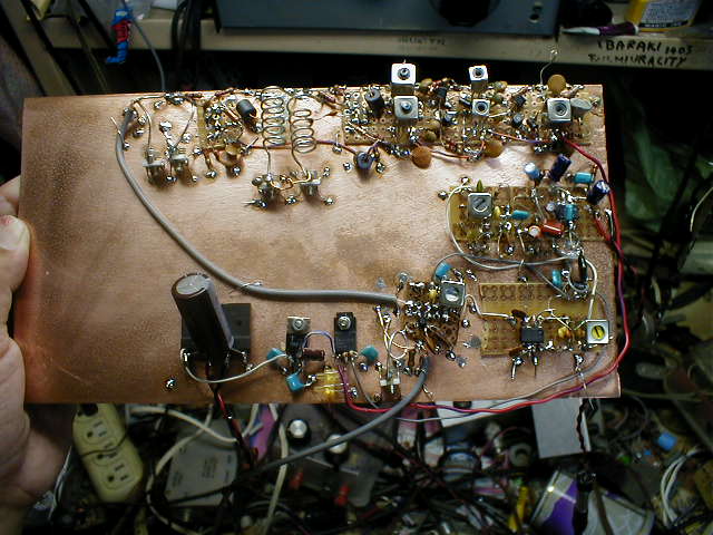
The reason of this production: In Japan, there are many local repeater
in many towns. They receive 434,xxMHZ and re- transmit the same signal
with 439.xxMHz. In my town we have KIDAMARI repeater. It exists only 3km
didtance from my home. It receive 434.70MHz and transmit it in 439.70MHz.
This repeater is used in "roll call meeting" in my Tsuchiura
Amateur Club. To receive this Roll call, I made this gear.
Block diagram
|
|
Antenna
439.70MHz
FM signal |
go
right |
mixer
converter |
255kHz
IF
signal |
MC1350P
IF amolifier |
Wise
Detecter |
Buffer
AF AMP |
LM386
Power
AMP |
Speaker
Jack |
8ohms
Speaker |
|
|
|
|
upper |
|
|
|
|
|
|
|
3rd Overtone
osccilator
genarate 27.466MHz |
1st
Doubler |
2nd
Doubler |
3rd
Doubler |
4th Doubler
makes
439.456MHz |
|
|
|
|
|
|
|
Explanation of Block Diagram: This is simple single conversion super Heterodyne
Radio. Very simple. But it need many circuits to generate UHF local signal.
In order to get 439.456MHz local signal , it need the 3rd overtone oscillator
and four stages of doubler. Antenna receives 439.70MHz FM signal. And this
signal is mixed in mixer converter with 439.456MHz local oscillator signal.
It outputs 244kHz FM signal as the difference of them. This Inter frequency
(IF) signal is amplified with MC1350P IC amplifier. And this IF is detected
with "Wise detector" made with two 1N60 Germanium diodes. There
comes audio signal. It is amplified with 2sk241 Buffer amplifier and LM386
Power amplifier. 2sk241 Buffer is used as impedance transducer. "Wise
detector" has high impedance output. Therefore it must received with
high impedance in the next stage.
Explanation of each stages of circuits: I will explain one by one in turn
of making.
1. At first ,please make the third overtone crystal oscillator! This oscillator
is made with junk 27MHz crystal. In Japan we use 27MHz band for CB communication.
Therefore it is very easy to get 27MHz junk crystal in the junk shops in
Akihabara city. I got it from the bag of my stock crystals. After making
this stage, please attach the dummy load 50 ohm resister on the (A) point
on the drawing! And please make it sure that you get real 27.466MHz signal
and the signal level of it should be more than 5mW,using frequency counter
and volt meter of spectrum analyzer!
2. Next, please make 1st doubler! This type of doubler is called as "Push
Push Doubler". I learned this type of doubler on the ARRL handbook.
I like this doubler very much because it works very steadily. T1 divides
the oscillated 27.466MHz signal for two counter phased signals. 0 degree
signal drives upper transistor. 180 degree signal drives downward transistor.
These two transistor drives the same tank coil. Therefore this tank coil
is driven on the timing of 0 degree and 180 degree. It is driven two times
in one cycle of input signal. Therefore this stage works as doubler. The
output of the doubler is constructed with double tank circuits. They purifies
the signals very well. After you make this stage, please attach the 50
ohm dummy load on the (B) point! And make it sure to get 54.932MHz over
5mW signal with test instruments!
3. Second Doubler is made with the same circuit with first doubler. 2SC381
is cheap HF transistor. But it was acceptable with this frequency. ( But
it is not acceptable in next stage. I tried and learned about it.) After
making this stage, please make it sure by attaching the load for (C) points
with some test instruments.
4. Next stage is also push push doubler. The output of this stage is 219.728MHz.
Here we can not use the sold coil with core. I made the tank coil with
1.2 diameter copper wire winding it around the red pencil for six turns.
One side of this coil is soldered on the ground and this side is called
as cold end. Another side of the coil is soldered for the 5pF trimmer capacitor.
This is called as hot end. Besides, all the variable and trimmer capacitor
has it's coid end and hot end. Please be care to use the hot end of the
trimmer as hot end of the coil ! And please solder the cold end of trimmer
capacitor on the groung pattern. Please tune tap point of the coils to
get best powerful output signals! After making this stage, please attach
the 50 ohm dummy load on the (D) point! Tune the trimmer capacitor! And
make it sure correct doubled signal came up!
5. The fourth doubler is also push push doubler. Here the tank coil do
not have an shape of coil any more but shaped only bar. Please cut 1.2mm
diameter copper wire for 50mm long! Solder one side of this wire on the
ground port! Solder the another side on the 3pF trimmer capacitor! Arrange
this assembly side by side with 10mm distances. The output tap is 20mm
from coil end. Attach there the coax cable. The outside of coax cable shall
be twisted two party and soldered on the ground. This manner makes the
low loss.If you make these completely, you can here the non modulated 439.456MHz
signal with the 430 handy transceiver.
6. Next, please make the Audio Power amplifier! I will not explain many
about it. It is the standard circuit using the LM386. After making it ,please
make the work of this circuit sure ,by inputting the audio signal on the
input of this amplifier.
7. Please make the audio buffer priamp ! This amplifier do not intend the
gain. This amplifier intend for the impedance match. The output impedance
of the detector is 200k ohms. Therefore I can not connect the LM386 directly.
After making the buffer, please make it sure that the job of this circuit
by input the audio signal on the (G) point of the diagram! This buffer
has 20dB gain. Total audio gain is about 60dB.
8. Very Sorry! I learned about FM detection on Japanese textbook. Therefore
I do not know correct English about it. Ratio detector needs a special
coil designed to use FM detection. It is not easy to get it in Japan. The
detector here I introduced is called as " Wise detector" . I
guess the "Wise" may be the name of the developer. This circuit
do not need the special transformer. I can use 455kHz AM coil for it, only
changing the frequency by adding the capacitor. By adding 470pF , the frequency
of this coil becomes 244kHz. After making this circuit, I connect the signal
generator on the (H) point and with changing the frequency, I noted the
output voltage of this detector. Please see the right side of the circuit
diagram! Here I show you the character of this FM detector.
9. I have Motorola handbook. This circuit with MC1350p is the standard
circuit as IF amplifier. I input the 244kHz signal on the (I) point. I
note the voltage gain between (H) and (I) point has 28dB.
10. At last we came the last part of this gear. I made one time this radio
with diode mixer. But the radio had poor gain. So I changed it with active
mixer. I completed it! In Japan we can get these Garium FET very cheap.
The price of 3SK113 was only 10 yen in Akihabara. Please care not to make
long the lead wire of this UHF circuit. You should connect each parts with
only 5mm!!! After making hole circuit, you may test this radio by transmitting
with 439.70MHz by the handy transceiver with the Dummy load on the another
room.
circuitdiagram...kidamari22.gif
Introduction of Transistors
2SC1815:Maker=Toshiba: Usage=audio AMP: Pc=400mW: ft=80MHzHfe=70b to700
2SC381:Maker=Toshiba: Usage=RF AMP: Pc=100mW: ft=250MHzHfe=25 to140
2SC3130:Maker=Matsushita: Usage=RF AFAMP: Pc=150mW: ft=1900MHzHfe=200typ
2SK113:Maker=Hitachi: Usage=UHFTVtuner: Pd=200mW: Idss 10 to 80mA: gm=10mSmin:
Crs=0.02pF: PowerGain=15dB(at900MHztypical)
2SK241:Maker=Toshiba: Usage=FMVHF RF Amplifier: Pd=200mW: Idss 0.6 to 12mA:
gm=2mSmin: Crs=0.04pF: PowerGain=24dB(at100MHztypical)
Introduction of coils and trans
T1,T2,T3,T4: FB801 trifilor 1t
T5,T6: 1.2mm diameter copper wire , winded around red pencil 6turn. Pull
it like coil spring of suspencion!
T7,T8,T9: 1.2mm diameter copper wire cut for 50mm long.
T10,T11,T12: detail unknown, made in Akihabara, 455kHz IF trans with capacitor,
Add 470pF to tune 244kHz. T11 and T12 must be center tapped.
The usage of this gear: I can receive the local repeater with merit 5 only
with 30mm vertical wire. But I feel the outer antenna can provide me more
noiseless signal.So I made 2element cubical quad. If you have your local
repeater, make it with your frequency. You can also make this gear with
the frequency favorite to your friends.
*****Description add on 23Sep2001****Transmittor for this KIDAMARI repeator
"434.70MHz FM 10MW transmittor***
To access my local 430 repeator, I made this ttransmittor. I can access
only 10mW and two element roop Yagi ,because this repeator is located omly
2 km from my shack. At first I will show you the block diagram.
Block diagram of 430 FM transmittor
Micro-
phone |
mic
AMP |
modulation
depth control |
go
under |
|
|
|
|
|
|
|
|
|
|
|
|
|
go
under |
|
|
|
|
|
|
|
|
|
|
88.5Hz tone
gene with
emittor folwer |
tone depth
control |
go right |
audio
mixer |
frequency
adjust |
VXO
oscillator
without coil
make
9.05625MHz |
triplor
make
|
buffer |
doubloer
1 |
doublor
2 |
doublor
3 |
doublor
4 |
430MHz
band pass
filtor |
ant |
kidamatx.gif
** T1,T2,T3,T4,T8 : FB801 0.2mm enamer wire trifilor 1t
** About 2sc1815,2sk241, 2Sc3130 please see the explanation on receiver
** 2SC1906: maker=Hitachi, usage= VHF amplifier,oscillator, mixer: Vcbo=30,
Pc=300mW, hfe=40min: ft=6--MHz: Power gain=18dB typ on 200MHz
**T5,T9 : 0.2mm enamel wire 10 turn around 300ohm 1/4 watt resistor
**T6,T7 : 1.2mm diameter wire 6 turn around 10mm diameter pencil , tapped
on 2turn from ground
**T10,T11 : 1.2mm diameter wire 1turn around 10mm diameter pencil , tapped
on 15mm from ground
Explanation of each block
***1. Microphone amplifier
***This amplifier is normal emitter grounded AMP. The magnitude of the
amplified signal should be adjusted as it*s proper level with the potentiometer
on the corrector of this AMP. After you completed this transmitter ,please
adjust here by monitoring the signal with the another receiver.
***2. Tone generator
***In order to activate the repeater ,we must mix 88.5Hz sign wave audio
signal with our sending audio signal. Sorry I am not sure this system is
the same with repeater of the another country or not. But anyway in Japan
tone is need. I made this 88.5Hz tone with this phase sift oscillator.
The tone is adjusted from 60 Hz to 90Hz by tone controlling 4.7k ohm potentiometer
on the phase sift circuit. The signal is picked from the collector of the
oscillator with the emitter follower. By the 1k ohm potentiometer on the
emitter of the follower, you should adjust the magnitude of the tone signal
as small as possible while the access to the repeater is possible. If the
signal of tone is too big, your friend hearing your signal through the
repeater must hear the "bu-bu-" tone with your speech. If the
tone signal is too small, you cannot activate the repeater.
***3. Audio mixer
*** Tone signal and your voice signal are mixed with one signal by this
mixer. This mixer activate the next VXO ( variable crystal oscillator)
directly without capacitor on it*s signal pass. Therefore the center voltage
of the VXO is tuned by the potentiometer on the corrector of the mixer.
*** 4. VXO
*** When I browse on the Akihabara electric parts shop, every time I browse
with a calculator and transistor handbook. About one month ago , when I
browse the city I discovered the vast of junk CB 27MHz crystals. On the
junk box I could discover 27.165 MHz named crystal. I made calculation
on the front of the shop. 16 times of 27.165MHz becomes 434.64 MHz. It
is quite near from the receiving frequency of my neighbor KIDAMARI repeater
, 434.70MHz. I bought this crystal. I made the VXO. This VXO can change
the oscillating frequency from 9.0543 to 9.0566MHz by changing the control
voltage of the variable capacitor diode. OK. It includes wanted 9.05625MHz.
48 times of 9.05625 MHz becomes 434.70MHz.
*** 5. Tripler
*** Please be care that in this circuit, the collector of two transistors
are connected on the another side of tank coil. This circuit is not "push
and push" but "push pull". The output signal of this circuit
was 1.0V to 50ohms. It was enough to activate the single transistor but
not enough to activate the double transistors. Therefore next Buffer amplifier
is need.
*** 6. Buffer
*** This is only single emitter grounded amplifier. It makes 27.16875MHz
1.8Vc-p (center to peak signal) 32mW for 50 ohm load.
*** 7. Doubler1
*** This is "push and push" doubler. It makes 54.3375MHz signal.
*** 8. Doubler2
*** It makes 108.675 MHz signal. The transistor used here is 2SC1906. The
ft of this transistor is 600MHZ. It works very well.
***9. Doubler3
*** It makes 217.35 MHz signal. The transistor used here is 2SC3130. The
ft of this transistor is 1900MHZ. It works very well. AT first I used here
the transistor named 2SC2644. The ft of this transistor is 4000MHz. This
transistor made an self oscillation, and flows very big collector current,
and the transistor has broken. You may not be able to get the same transistor.
But anyway you shall choose the transistor who has proper ft. I say again
here that the ft frequency of the transistor should be about 10 times higher
than the dealt frequency of each stage.
***10. Doublor4
*** It makes the wanted434.70 MHz signal. The transistor used here is 2SC3130.
The ft of this transistor is 1900MHZ. The ft of this transistor is a little
low than the 10 times of the dealt frequency. Therefore the output is lower
than another last stages. It should not drive next doubler. But it worked
safety and generated 10mW output signal. I could access the local repeater
with this machine and two element cubical quad antenna mounted on the window
of my shack located on the second floor of my house. You should tune the
430MHz ban pass filter on the output end of this transmitter. You should
make " cut and try" about the length of the T10 and T11 from
40mm to 60mm. You should tune the distance between T10 and T11 from 10mm
to 2mm. You should tune the vest point of tap to connect the 56p farad
capacitor and to connect the coaxial cable from 20mm to 10mm distance from
the ground.
*** I constructed this transmitter on the non printed board like the receiver.
I putted it on the same case from the receiver. I used the push momentary
switch with two circuits. One circuit of the switch is used to change the
antenna connection to receiver or transmitter. Another one circuit of the
push switch is used to change the power voltage 12 volt connection to receiver
or transmitter. You should not use snap switch for this purpose. If you
forget to turn to receiving position , you should make jamming to your
local repeater 24 hours. You can understand that you should avoid it.
*********Description add on 6 Oct 2001 *** Crystalization of the tone genarator****
I operated with this transceiver for one week. I jointed in the roll call
of my local club and made contact with few stations. But I could not access
the repeater with 100%. When I failed to access , I could access when I
tuned the tone frequency adjusting potentiometer. But on the next day,
I must tune it once again. Therefore I felt that this tone generator lacks
the frequency stability. So I decided to make the tone generator with crystal.
But the crystal can not generate the wanted 88.5Hz directly. The crystal
generate the high frequency. So I must divide the crystal generator. I
wrote the frequency wanted as follows. 88.5Hz...177Hz...354Hz...708Hz..........2.899968Mhz,5.799936MHZ,11.599872MHz.
I looked for the just crystal from the kilograms of my crystal stocks.
I discovered the 11.5796MHz named crystal. I made the Mos IC inverter as
you can see on the following drawing. And I tuned the capacitor named Cc
as 22pF. I got 11.578MHz. Yes, It is near enough from the wanted 11.57999MHz.
There I used the 74HC640 as inverter. You shall use the 74HC04. After that
I attached the 74HC4040 12 stage divider. And after that I attached also
74HC4040 as 5 stage divider. The old man on my local says that he could
access the repeater with RC generated tone. I feel you may be able to use
the original RC generator if you choose the temperature stable type capacitor.
kidamaritone.gif
栘揷梋乮偒偩傑傝乯儗僺乕僞愱梡係俁俋丏俈侽俵俫倸俥俵愱梡庴怣婡
惢嶌偺宱堒丗巹偺壠乮搚塝巗拞恄棫挰乯偐傜俁倠倣傎偳偺儘乕僇儖偵栘揷梋乮偒偩傑傝乯儗僺乕僞偲偄偆儘乕僇儖儗僺乕僞偑桳傝傑偡丅巹偺強懏偟偰偄傞
俰俙俼俴搚塝僋儔僽偲偄偆抧堟僋儔僽偱偼丄枅廡寧梛偺栭俋帪偐傜丄偙偺儗僺乕僞傪巊偭偰儘乕儖僐乕儖儈乕僥傿儞僌偑峴傢傟傑偡丅偙偺儘乕儖僐乕儖儈乕僥傿
儞僌偺忣曬傪曔傜偊傞偲偄偆嬌傔偰幚梡揑側栚揑偱偙偺惢嶌傪峴偄傑偟偨丅
僽儘僢僋僟僀傾僽儔儉
|
|
|
|
傾儞僥僫
439.70MHz
FM |
仺 |
儈僉僒乕
僐儞僶乕僞乕 |
仺
244kHz
FM |
拞娫
廃攇
憹暆婍 |
俥俵
専攇婍 |
仺 |
掅廃攇娚徴
憹暆婍
|
掅廃攇
揹椡憹暆婍 |
僗僺乕僇乕 |
|
|
|
|
|
|
仾 |
|
|
|
|
|
|
|
俁攞
僆乕僶僩乕儞
敪怳婍
俀俈丏係俇俇俵俫倸
弌椡 |
仺 |
戞堦
掽攞婡 |
戞俀
掽攞婡 |
戞俁
掽攞婡 |
戞係
掽攞婡 |
439.456
MHz
嬊敪弌椡 |
|
|
|
|
|
|
|
僽儘僢僋僟僀傾僌儔儉偺愢柧
倀俫俥偺婡婍偺惢嶌偼壗偑戝曄偐偭偰偄偆偲丄乽嬊敪偑懡抜偵側傝丄夞楬婯柾偲偟偰柺搢偔偝偄丅乿偲偄偆帠偩偲憐偄傑偡丅崱夞偼屌掕廃攇悢偺庴怣婡偱偡偑丄
夞楬恾傗僽儘僢僋僟僀傾僽儔儉傪尒偰偄偨偩偄偰敾傞傛偆偵丄庴怣婡慡懱偺傎傏敿暘偑嬊敪偱偡丅偙偺庴怣婡偼慡懱偲偟偰偼丄嬌傔偰婎杮揑側偄傢備傞僔儞僌儖
僐儞僶乕僕儑儞乮侾夞偩偗廃攇悢曄姺偡傞僞僀僾乯偺僗僷乕僿僥儘僟僀儞庴怣婡偱偡丅傾儞僥僫偐傜棃偨怣崋乮係俁俋丏俈侽俵俫倸乯偼丄嬊敪怣崋偺
係俁俋丏係俆俇俵俫倸偲崿崌偝傟偰丄嵎偺俀係係倠俫倸偵曄姺偝傟傑偡丅偙偺拞娫廃攇怣崋偑拞娫廃攇憹暆婍偱俀俉倓俛憹暆偝傟丄俥俵専攇婍乮儚僀僘専攇婍乯
偱専攇偝傟偰掅廃攇怣崋乮亖壒惡怣崋乯偵側傝傑偡丅偙偺宍幃偺俥俵専攇婍偼弌椡僀儞僺乕僟儞僗偑崅偄偺偱丄掅廃攇憹暆婍偺弶抜偵偼擖椡僀儞僺乕僟儞僗偺崅
偄俥俤俿憹暆婍傪巊偭偰偄傑偡丅偙偺掅廃攇怣崋偼丄偝傜偵掅廃攇揹椡憹暆偲偟偰掕斣偲側偭偨俬俠憹暆婍偱偁傞俴俵俁俉俇偵傛偭偰憹暆偝傟傑偡丅偙偺掅廃攇
憹暆婍偼俥俤俿偺弶抜偑俀侽倓俛乮幚應乯偁傞偺偱丄師偺俴俵俁俉俇偼丄偄傢備傞嵒懞夞楬偲偣偢偵丄晛捠偵係侽倓俛憹暆偟偰偄傑偡丅偝偰丄嬊敪偵榖傪堏偟傑
偟
傚偆丅嬊敪偺弶抜偼27.456MHz偺俁攞僆乕僶乕僩乕儞敪怳婍偱偡丅偙偺怣崋傪掽攞婡偺係楢嵔乮僗乕儗儞僠儍儞乯偱俀偺係忔攞偡側傢偪侾俇掽攞偟偰
439.456MHz偺怣崋傪摼偰偄傑偡丅
奺晹偺愢柧偲専嵏屄強
偙偙偱偼丄夞楬侾屄偢偮弴斣偵丄幚嵺惢嶌偡傞弴斣偵偦偭偰丄夞楬偺愢柧偲専嵏偺庤弴傪愢柧偟傑偡丅
侾丏傑偢嵟弶偵嶌傞偺偼俀俈丏係俇俇俵俫倸偺敪怳婍偱偡丅俀俈俵俫倸偺悈徎偼崱偱傕僕儍儞僋偱埨偔擖庤偑壜擻偱偡丅偙偺埨偄俀俈俵俫倸偺悈徎傪巊偭偰
係俁侽俵俫倸偺婡婍偑嶌傟傞偲偄偆偺偑偙偺惢嶌偺戞堦偺傒偦偱偡丅偙偙偱偼丄婘偺忋偵揮偑偭偰偄偨俀俽俠侾俉侾俆傪巊偭偰慻傒傑偟偨丅慻傫偩傜乮俙乯揰偵
俆侽僆乕儉偺晧壸傪偮側偄偱丄偙偺晧壸偺椉抂偵廃攇悢寁應婍偲揹埑應掕婍傪偮側偄偱丄偪傖傫偲俀俈丏係俇俇俵俫倅偺怣崋偑揹埑侾丏俀倁們亅倫乮愲摢抣儃儖
僩乯偱弌偰偄傞帠傪妋擣偟偰偔偩偝偄丅
俀丏師偵偙偺俀俈俵俫倸偺怣崋傪俀掽攞偟偰俆係俵俫倸偺怣崋偵偡傞僟僽儔乕傪嶌傝傑偡丅偙偺僞僀僾偺僟僽儔乕偼丄乽僾僢僔儏僾僢僔儏傾僋僥傿僽僟僽儔乕乿
偲屇偽傟傞夞楬偱丄俙俼俼俴偺僴儞僪僽僢僋偵嵹偭偰偄偨傕偺偱偡丅俥俛俉侽侾偱嶌偭偨僩儕僼傽僀儔乕姫偺崅廃攇僩儔儞僗偱丄慜偺俀俈俵俫倸偺怣崋偺惓憡偲
媡憡偺怣崋傪庢傝弌偟偰丄偙傟傪僩儔儞僕僗僞乕偱憹暆偟偰僞儞僋僐僀儖傪嬱摦偟傑偡丅俀俈俵俫倸偺惓偺敿僒僀僋儖偲晧偺敿僒僀僋儖偱弌椡偑弌傞偺偱丄寢壥
揑偵侾僒僀僋儖偱俀夞嬱摦偝傟傞偺偱丄俀掽攞偑払惉偝傟傞偲偄偆偟偔傒偱偡丅僟僽儔乕偺弌椡偼暋摨挷偵側偭偰偍傝丄栚揑廃攇悢埲奜偺怣崋傪廫暘偵梷埑偟偰
偄傑偡丅偙偺僞僀僾偺僟僽儔乕偼丄摦嶌偑妋幚側偺偼椙偄偺偱偡偑丄側偵偟傠俠媺偺僩儔儞僕僗僞乕傪俀屄傕嬱摦偟側偔偰偼側傜側偄偺偱丄擖椡揹椡偲偟偰偼寢
峔昁梫偱偡丅俆侽僆乕儉晧壸偱侾倁們乕倫偮傑傝俆倣倂埲忋偱嬱摦偟側偄偲丄懱尡揑偵傑偲傕偵嵎摦偟傑偣傫丅戞堦僟僽儔乕傪嶌偭偨傜丄乮俛乯揰偵俆侽僆乕儉
偺晧壸掞峈傪偮側偄偱丄椉抂偵俆係丏俋俁俀俵俫倸偺怣崋偑俆倣倂埲忋弌偰偄傞帠傪妋擣偟偰偔偩偝偄丅傕偪傠傫俥俠倅俆侽偺僐僀儖偺僐傾傪挷愡偟偰
弌椡嵟戝偵偟傑偡丅偦傟偐傜偙偺偱埖偆廃攇悢偼俆係俵俫倸偱偡偺偱丄偙偺抜偺僩儔儞僕僗僞乕偼俫俥憹暆梡偺僩儔儞僕僗僞乕側傜俷俲偱偡丅俀俽俠俁俉侾偺僄
儈僢僞乕偺強偵擖偭偰偄傞俀俀僆乕儉偺掞峈偼揹棳晧婣娨傪偐偗偰偄傑偡丅偙偺掞峈傪彫偝偔偟偰備偔偲丄弌椡偼戝偒偔側傝傑偡偑丄敪怳偟偰偟傑偆婋尟傕惗偠
傑偡丅僟僽儔乕偑敪怳偟偨帪偵偼丄僐僀儖偺僐傾乕傪夞偟偰傕摨挷偑偲傟側偄偺偱丄敾傝傑偡丅傕偪傠傫丄偦偺抜偺攇宍傪捈愙娤嶡偱偒傞僆僢僔儘僗僐乕僾傗僗
儁傾僫摍傪偍帩偪側傜丄偦傫側愢柧偼晄梫偱偡丅
俁丏戞擇掽攞婡傕廃攇悢偑攞偵側偭偨偩偗偱丄戞堦掽攞婡偲摨偠夞楬偱偡丅俀俽俠俁俉侾偼倖倲偑俀俆侽俵俫倸偱偡偑丄偙偙傑偱偼栶偵偨偪傑偟偨丅偙偺夞楬傪慻傫偩傜丄乮俠乯揰偵俆侽僆乕儉偺掞峈晧壸傪偮側偄偱丄侾侽俋丏俉俇係俵俫倸偺怣崋傪丄慜偲摨偠傛偆偵妋擣偟傑偟傚偆丅
係丏戞嶰掽攞婡偼夞楬尨棟揑偵偼偙傟傑偱偺掽攞婡偲摨偠僾僢僔儏僾僢僔儏僟僽儔乕偱偡丅扐偟丄埖偆怣崋偑偨偐偄偺偱丄倖倲偺崅偄俀俽俠俁侾俁侽偵偟偰偁傝
傑偡丅俀俽俠俁侾俁侽偺倖倲偼侾俋侽侽俵俫倸側偺偱丄係俁侽偺婡夿偺嶌惉偵偼妝彑偱巊偊傑偡丅傾僉僶偺僕儍儞僋壆偱偨偟偐侾侽杮僙僢僩偱侾侽侽墌偔傜偄偺
暔偱偡丅偙偺僩儔儞僕僗僞乕偼柺幚憰僞僀僾側偺偱丄係偮傔婎斅偵偦偺傑傑揬傝晅偗偵偟偰巊偄傑偡丅係偮傔婎斅偵揬傝晅偗偵偡傟偽僠僢僾晹昳傕偦偺傑傑巊偊
傑偡偺偱丄偙傟偐傜偼擖庤偑埨偄僠僢僾晹昳傪偳傫偳傫巊偄傑偟傚偆丅偙偺僟僽儔乕偺弌椡廃攇悢偼丄俀侾俋丏俈俀俉俵俫倸偱偡偺偱丄偙傟傑偱偺傛偆側僐傾擖
傝儃價儞偱偼摨挷偑偲傟傑偣傫丅俿俆偼侾丏俀倣倣宎偺儊僢僉摵慄傪娵偄墧昅偵俇偐偄姫偄偰丄偙傟傪帺摦幵偺僒僗儁儞僔儑儞僐僀儖偔傜偄偺宍偵彮偟怢偽偟偰
嫟怳僐僀儖偲偟傑偡丅偙偺僐僀儖偺曅曽偼傋偨傾乕僗偺摵斅偵敿揷晅偗偟傑偡丅傕偆曅曽偼丄僩儕儅乕僐儞僨儞僒乕偺儂僢僩僄儞僪懁偵偼傫偩晅偗偟傑偡丅僩儕
儅乕偺僐乕儖僪僄儞僪偼傕偪傠傫儀僞傾乕僗偟傑偡丅僩儔儞僕僗僞乕偺嫟捠僐儗僋僞乕偐傜俆俇倫俥偺僷僗僐儞傪捠偟偰俿俆嫟怳婍偵媼揹偟傑偡丅媼揹
揰偼俿俆僐僀儖偺僐乕儖僪僄儞僪偐傜俀丏俆姫傎偳忋偵忋偑偭偨偲偙傠偱偡丅偙偺俿俆偲俿俇傕暋嫟怳峔憿偲偟丄摦嶌偺妋幚傪偹傜偄傑偟偨丅偙偙傑偱慻傫偩
傜丄乮俢乯揰偵晧壸傪偮側偘丄弌椡嵟戝偵挷惍偟傑偟傚偆丅巹偺庤帩偪偺應掕婍偱偼偡偱偵偙偙偼寁應晄壜擻椞堟側偺偱丄乮俢乯揰偺弌椡傪僎儖儅僯僂儉僟僀
僆乕僪侾俶俇侽偱専攇偟偰揹埑嵟戝偵挷惍偟倲偩偗偱偡丅
俆丏師偺戞巐掽攞婡傕傑偨丄僾僢僔儏僾僢僔儏僟僽儔乕偱偡丅偙偙偱偼丄弌椡偑係俁侽俵俫倸側偺偱丄嫟怳懱偼偡偱偵僐僀儖偺懱傪側偝偢丄偨偩偺朹偱偡丅懡彮
攝慄偺搒崌偱傑偑偭偰傕丄偁傞偄偼寉偔侾僞乕儞姫偄偰傕偐傑偄傑偣傫丅愭傎偳偲摨偠侾丏俀倣倣宎偺儊僢僉摫慄傪俆侽倣倣側挿偝偵愗偭偰巊偭偰偔偩偝偄丅偙
偙傕暋摨挷偲偟丄拞娫偵僞僢僾傪偲偭偰媼揹偟傑偡丅俿俈偲俿俉偼丄僐儞僨儞僒乕偱偮側偑側偄偱傕丄侾侽倣倣偺嫍棧偱偍偄偰偍偔偩偗偱丄揹帴寢崌偟偰儕儞僋
偟傑偡丅俿俉偺僞僢僾偐傜揔摉側俁們俀倁偲偐侾丏俆俢俀倁偲偐偺摨幉働乕僽儖偱丄弌椡傪庢傝弌偟傑偡偑丄摨幉偺奜懁偺栐慄偼侾杮偵偨偽偹傞偺偱偼側偔丄彈
偺巕偺偍偝偘偺條偵俀杮偵暘偗偰丄懇偹偰偙傟傪椉曽傾乕僗偵敿揷晅偗偡傞傛偆偵偡傞偲丄怣崋偑儘僗柍偔揱傢傝傑偡丅偄偭傐偆丄摨幉働乕僽儖偺恈慄偺曽偼丄
傓偒弌偟晹暘偺挿偝傪俆倣倣埲壓偵偟偰偔偩偝偄丅偙偙傑偱嶌偭偨傜丄乮俤乯揰偺弌椡傪妋擣偟丄弌椡嵟戝偵惉傞傛偆偵億僥儞僔儑儊乕僞傪挷惍偟傑偡丅僞僢僾
偺埵抲傗嫟怳朹偺挿偝偼挷惍偑昁梫偐傕偟傟傑偣傫丅偙偙傑偱偔傞偲丄乮俤乯揰偵俆侽僆乕儉偺僟儈乕儘乕僪傪偮側偄偩忬懺偱摦嶌偝偣偰偍偔偲丄棧傟
偨応強偱丄係俁俋丏係俆俇俵俫倸偺怣崋偑儌僯僞乕偱偒傑偡丅壠偺拞側傜偳偙偱傕儊儕俆偱偟偨丅偙傟偱惢嶌偼敿暘偱偡丅
俇丏師偵丄掅廃攇揹椡憹暆婍傪偮偔傝傑偡丅俴俵俁俉俇傪巊偭偨掕斣偺夞楬偱偡丅摿偵愢柧偼偟傑偣傫丅偙偺夞楬傕丄堦墳弌棃偨傜乮俥乯揰偐傜掅廃攇怣崋傪偄傟偰憹暆婍偺摦嶌傪妋擣偟偰尒傑偟傚偆丅
俈丏俴俵俁俉俇偺慜偵俥俤俿偺僾儕傾儞僾偑擖傝傑偡丅慜偵傕弎傋傑偟偨偑丄偙偺僾儕傾儞僾偼憹暆搙傪摼傞偺偑栚揑偱偼偁傝傑偣傫丅俥俵専攇婍偺弌椡僀儞
僺乕僟儞僗偑俀侽侽倠僆乕儉側偺偱丄捈愙俴俵俁俉俇傪嬱摦偱偒側偄偺偱偡丅俥俤俿偺憹暆婍偺擖椡僀儞僺乕僟儞僗偼僎乕僩偺掞峈偱偄偔傜偵偱傕偱偒傞偺偱丄
偦偙偵俀侽侽倠僆乕儉傪偄傟偰僀儞僺乕僟儞僗惍崌偟偰偄傑偡丅偨偩偟丄偙偺僾儕傾儞僾偼丄幚應俀侽倓俛偺棙摼偑偁傝傑偟偨偺偱丄掅廃攇憤崌棙摼偲偟偰
俆侽倓俛偁傝傑偡偐傜丄廫暘偱偡丅偙偙傑偱丄偱偒偨傜堦墳乮俧乯揰偵掅廃攇怣崋傪擖傟偰摦嶌傪妋擣偟偰偍偒傑偟傚偆丅
俉丏師偵嶌傞偺偑丄専攇婍偱偡丅俥俵専攇婍偱桳柤側僼僅僗僞乕僔乕儗専攇婍偼丄摿暿側専攇梡僐僀儖偑昁梫側偺偱丄変乆傾儅僠儏傾偵偼晄岦偒偱偡丅偙偙偱巊
偆乽儚僀僘専攇婍乿偼丄扥塇偝傫偺乽僩儔儞僕僗僞乕僴儞僪僽僢僋乿偵嵹偭偰偄偨夞楬偱丄俙俵梡偺俬俥僐僀儖傪巊偭偰俥俵専攇偑偱偒傞偺偱曋棙偱偡丅巹偼丄
夞楬傪僐僺乕偟偰偮偐偭偰偄傞偩偗側偺偱丄摦嶌尨棟偼棟夝偟偰偄傑偣傫丅偨偩偟丄偙偙偱偺拞娫廃攇廃攇悢偼俀係係倠俫倅偲掅偄偺偱丄係俆俆倠俫倸梡偺崟偺
俬俥僐僀儖偵奜晅偗偱係俈侽倫俥傪捛壛偟偰嫟怳廃攇悢傪壓偘偰巊偭偰偄傑偡丅乮俫乯揰偐傜僔僌僫儖僕僃僱儗乕僞偺怣崋傪擖傟偰丄乮俧乯揰偺捈棳揹埑傪娤嶡
偟偨乽専攇摿惈恾乿傪丄夞楬恾偺塃壓偵偟傔偟偰偍偒傑偟偨丅
俋丏師偵俵俠侾俁俆侽俹偵傛傞拞娫廃攇憹暆婍傪嶌傝傑偡丅偙偺俬俠偑拞娫廃攇憹暆偵俧俷俷俢偱偁傞帠傕丄扥塇偝傫偑俠俻帍偱埲慜偛徯夘偔偩偡偭偨傕偺偱
偡丅偙偺俬俠偼僶儔儞僗弌椡乮僾僢僔儏僾儖弌椡乯偱摦嶌偡傞條偵偱偒偰偄傞偺偱丄俿侾侽偺僐僀儖偼丄侾師懁偑僙儞僞乕僞僢僾偵側偭偰偄傞暔傪慖傫偱偛巊梡
偔偩偝偄丅偨偩偟丄偔傟偖傟傕廐梩尨偺揦愭偱乽偙偺僐僀儖偼僙儞僞乕僞僢僾偱偡偐乕乿側傫偰恞偹柍偄條偵偹偑偄傑偡丅偍揦偺恖偵敾傞栿側偄偱偡傛丅偄傠偄
傠側揦偱係俆俆倠俫倸偺俬俥俿傪攦偄偁偝偭偰帋偟偰偔偩偝偄丅偙偙偺俬俥俿偵傕嫟怳廃攇悢傪壓偘傞奜晅偗係俈侽倫俥傪偍朰傟側偔丅偙偙傑偱弌棃偨傜丄
乮俬乯揰偐傜俀係係倠俫倸偺俙俵怣崋傪擖傟偰丄僺乕偲偄偆壒偑僗僺乕僇乕偐傜弌傞偺傪妋擣偟傑偟傚偆丅儚僀僘専攇婍偼丄俙俵彍嫀婡擻偑慡偔偁傝傑偣傫偺
偱丄俙俵怣崋傕姰慡偵専攇偱偒傑偡丅杮棃偼岲傑偟偄摿惈偱偼柍偄偺偱偡偑丄偙偆偄偆帪偼曋棙偱偡丅偪傖傫偲俙俵怣崋偑専攇丄憹暆偝傟偰偄傟偽晄梫側敪怳摍
柍偄帠傪妋擣偱偒偨帠偵側傝傑偡丅
侾侽丏偝偰丄嵟屻偑儈僉僒乕偱偡丅幚偼嵟弶偙偺儈僉僒乕偵偼僟僀僆乕僪俢俛俵傪巊偄傑偟偨偑丄棙摼晄懌偱偩傔偱偟偨丅偦傟偱僨儏傾儖僎乕僩俥俤俿傪巊偄丄
偽偭偪傝偱偟偨丅偙偙偱偮偐偭偨俁俽俲侾侾俁偼愭寧乮偨偩偄傑俀俀俰俴倄俀侽侽侾乯傾僉僶偺彫戲偝傫偱丄乽摿攧乿偲偟偰揤堜偐傜壓偑偭偰偄偨暔偱丄傗偼傝
侾侽屄侾侽侽墌偺暔偱偡偑丄倀俫俥俿倁僠儏乕僫乕梡偺僈儕徨慺偱偡丅俋侽侽俵俫倸偱偺棙摼侾俆倓俛偲偄偆傆偆偵僴儞僪僽僢僋偵偁傞偺偱丄偙偺傛偆側倀俫俥
偺儈僉僒乕偵偼懪偭偰偮偗偺愇偱偡丅偙偺俥俤俿偺戞堦僎乕僩偵偼傾儞僥僫偺怣崋乮係俁俋丏俈侽俵俫倸乯傪擖傟丄戞擇僎乕僩偵偼丄嬊敪偺怣崋
乮係俁俋丏係俆俇俵俫倸乯傪偄傟傞帠偵傛偭偰嵎偺俀係係倠俫倸偺怣崋傪庢傝弌偟偰拞娫廃攇怣崋偲偟傑偡丅幚應偱偒偰偄傑偣傫偑丄偙偙偱傕侾俆倓俛掱搙偺曄
姺棙摼偑摼傜傟偰偄傞暔偲悇掕偟傑偡丅戞堦僎乕僩偵偼俆侽倣倣偺摵慄偲俁倫俥偺僩儕儅乕偐傜側傞係俁侽俵俫倸嫟怳懱傪偮側偘丄偙偺嫟怳懱偵挿偝俀侽倣倣偺
儕儞僋僐僀儖乮偲偄偭偰傕偩偩偺摵慄傪偦偽偵偼傢偣偨偩偗偺帠乯傪拝偗偰丄偙傟偵傾儞僥僫偐傜媼揹偟傑偡丅椺偵傛偭偰丄俥俤俿偺僎乕僩偲嫟怳懱僞僢僾偲偺
儕乕僪
偺挿偝偼侾侽埲壓偱偱偒傟偽俆倣倣掱搙偵側傞傛偆偵偟偰偔偩偝偄丅係俁俋丏俈侽俵俫倸偺僔僌僫儖僕僃僱儗乕僞乕摍偍帩偪偺曽偼偄側偄偱偟傚偆丅係俁侽偺僴
儞僨傿乕僩儔儞僔乕僶乕偵僟儈儘乕僪傪晅偗偰丄椬偺晹壆偐側傫偐偐傜帋尡揹攇傪偩偣偽丄暦偙偊傞偼偢偱偡丅
夞楬恾...kidamari22.gif
夞楬恾偺拞偺僐僀儖偲僩儔儞僕僗僞乕偺摿惈
Introduction of Transistors
2SC1815:Maker=Toshiba: Usage=audio AMP: Pc=400mW: ft=80MHzHfe=70b to700
2SC381:Maker=Toshiba: Usage=RF AMP: Pc=100mW: ft=250MHzHfe=25 to140
2SC3130:Maker=Matsushita: Usage=RF AFAMP: Pc=150mW: ft=1900MHzHfe=200typ
2SK113:Maker=Hitachi: Usage=UHFTVtuner: Pd=200mW: Idss 10 to 80mA: gm=10mSmin:
Crs=0.02pF: PowerGain=15dB(at900MHztypical)
2SK241:Maker=Toshiba: Usage=FMVHF RF Amplifier: Pd=200mW: Idss 0.6 to 12mA:
gm=2mSmin: Crs=0.04pF: PowerGain=24dB(at100MHztypical)
Introduction of coils and trans
T1,T2,T3,T4: FB801 trifilor 1t
T5,T6: 1.2mm diameter copper wire , winded around red pencil 6turn. Pull
it like coil spring of suspencion!
T7,T8,T9: 1.2mm diameter copper wire cut for 50mm long.
T10,T11,T12: detail unknown, made in Akihabara, 455kHz IF trans with capacitor,
Add 470pF to tune 244kHz. T11 and T12 must be center tapped.
巊梡姶偲墳梡丗俀侽們倣傎偳偺悅捈側揹慄傪晅偗偨偩偗偱丄儊儕俆偱擖姶偟偰偄傑偡丅偨偩偟丄偪傖傫偲壆奜傾儞僥僫傪晅偗偨曽偑丄僲僀僘偑傊偭偰俽俶偑椙偔
側傞偺偱丄俀僄儗偺俠俻傪嶌偭偰巊偭偰偄傑偡丅奆偝傫傕儘乕僇儖偵儗僺乕僞偑偁傞側傜丄偦偺廃攇悢偵偁傢偣偰嶌傜傟傞偲丄屼嬤強偺忣曬偑擖偭偰偄偄偲憐偄
傑偡丅偁傞偄偼丄桭恖偲偺楢棈廃攇悢愱梡偺屌掕廃攇悢庴怣婡偲偟偰側傜丄儗僺乕僞偱側偔偲傕棙梡壙抣偑偁傞偱偟傚偆丅偙偺嬊敪傪悈徎愗傝懼偊偵偟偨傝丄
俹俴俴偱廃攇悢愗傝懼偊傪偡傟偽懡僠儍儞僱儖俥俵庴怣婡偵側傝傑偡丅偦傟偐傜丄拞娫廃攇傪係俆俆倠俫倸偦偺傕偺偱嶌傟偽丄僙儔儈僢僋僼傿儖僞乕傪乮俬乯揰
偵擖傟偰丄嬤愙廃攇悢偺崿怣傕傆偣偘傑偡偺偱丄偄偭偦偆杮奿揑側庴怣婡偵側傝傑偡丅
婰嵹捛壛 丗 俀侽侽侾擭俋寧俀俁擔 丗 憲怣晹偺捛壛
庴怣婡偲偟偰偟偽傜偔巊偭偰偄傑偟偨偑丄憲怣傕偟偰傒偨偔側傞偺偼帺慠偺惉傝峴偒偲偄偆傕偺偱偟傚偆丅偨傑偨傑廐梩尨偱椙偄悈徎偑擖庤偱偒偨偺偱丄憲怣婡傪嶌傝傑偟偨偺偱丄徯夘偟傑偡丅
僽儘僢僋僟僀傾僌儔儉
| 儅僀僋傾儞僾 |
儅僀僋曄挷搙挷惍 |
仺 |
伀 |
|
|
|
|
|
|
|
|
|
|
|
|
|
伀 |
|
|
|
|
|
|
|
|
|
|
僄儈僢僞乕僼僅儘傾乕晅偒
埵憡敪怳婍
乮俉俉丏俆俫倸僩乕儞怣崋敪惗乯 |
僩乕儞怣崋嫮搙挷惍 |
仺 |
僆乕僨傿僆
儈僉僒乕 |
廃攇悢
旝挷惍 |
倁倃俷
敪怳婍
9.05625MHz
敪怳弌椡 |
俁攞
掽攞婍 |
娚徴
憹暆婍 |
戞侾
俀攞
掽攞婍 |
戞俀
俀攞
掽攞婍 |
戞俁
俀攞
掽攞婍 |
戞係
俀攞
掽攞婍 |
434MHz
僶儞僪僷僗僼傿儖僞乕 |
傾儞僥僫 |
kidamatx.gif
奺抜偺愢柧
仏仏仏侾丏儅僀僋傾儞僾
仏仏仏儅僀僋傾儞僾偼晛捠偺僄儈僢僞乕愙抧憹暆婍偱偡丅巹偺巊偭偰偄傞僟僀僫儈僢僋儅僀僋偺弌椡偼俆侽倣倁們乗倫掱搙偺揹埑偑弌傞偺偱丄偙偺傾儞僾偱
俀侽倓俛傕憹暆偟偰丄俆侽侽倣倂偵側傞偲彮偟戝偒偡偓傞偺偱丄弌椡偺強偺億僥儞僔儑偱俁侽侽倣倁們亅倫掱搙偵側傞傛偆偵壛尭偟傑偡丅嵟屻偼丄儗僺乕僞乕傪
捠偟偰暦偒傗偡偄掱搙偺嵟廔挷惍偟傑偡丅
仏仏仏俀丏僩乕儞僕僃僱儗乕僞乕
仏仏仏僩乕儞僕僃僱儗乕僞乕偵偼偄偔偮偐偺曽幃偑偁傝傑偡偑丄娙扨偵埵憡敪怳婍偱嵪傑偣偰偄傑偡丅埵憡夞楬偺強偺係丏俈倠僆乕儉偺敿屌掕掞峈傪挷惍偡傞
偲丄敪怳廃攇悢偑俇侽俫倸偐傜俋侽俫倸傑偱挷惍偱偒傑偟偨丅僆僢僔儘僗僐乕僾偱偩偄偨偄偁傢偣偰偍偄偰丄嵟廔揑偵偼丄偙偙傕偆傑偔儗僺乕僞乕偑乽傂偭偐偭
偐偭偰偔傟傞乿條偵偁傢偣崬傒傑偡丅彯丄偙偙偺敪怳廃攇悢偼丄揹尮揹埑偵傕埶懚偟偰曄壔偟傑偡偺偱丄偐側傜偢埨掕壔偟偨揹尮傪巊偄丄挷惍帪偲慻傒崬傒屻偱
揹埑偑曄傢傜側偄條偵偟偰偔偩偝偄丅傑偨丄僩乕儞偼偒傟偄偵挻偟偨帠偼偁傝傑偣傫偑丄僆僢僔儘偱尒偨栚彮偟榗傫偱偄偰傕戝忎晇偱偡丅偙偙偺弌椡偺僀儞僺乕
僟儞僗偼俀俀倠側偺偱丄儈僉僒乕偵捈愙僽僠僐儉偺偼偐傢偄偦偆偱偡偐傜丄僄儈僢僞乕僼僅儘傾乕傪擖傟丄偙偙偱摨帪偵僩乕儞弌椡偺揹埑怳暆挷惍傕偟偰偄傑
偡丅僩乕儞怣崋偼儅僀僋怣崋偺侾侽暘偺侾掱搙偱偄偄傜偟偔丄挷惍屻偼俆侽倣倁們亅倫掱搙偱偟偨丅億僥儞僔儑偺僟僀傾儖偼傎偲傫偳傾乕僗懁偵傊偽傝偮偄偰偄
傑偡丅
仏仏仏俁丏僆乕僨傿僆儈僉僒乕
仏仏仏僩乕儞怣崋偲儅僀僋偺壒惡怣崋傪崿偤崌傢偣傞偺偑偙偙偺栶栚偱偡丅俀俽俲俀係侾偱寉偔憹暆偟側偑傜崿崌偟偰偄傑偡丅俀俽俲俀係侾偺僪儗僀儞揹棳偼丄
偙偙偑僶僀傾僗偝傟偰偄側偄偺偱丄俬倓倱倱偩偗棳傟傑偡丅偙傟偼寛傑偭偨揹棳側偺偱丄偦偺僪儗僀儞揹棳偵僪儗僀儞偺掞峈偺揹埑崀壓偍妡偗偨暘偑僪儗僀儞掞
峈偺弌椡揹埑偵側傝傑偡丅偱偡偐傜丄偙偺儈僉僒乕偺僪儗僀儞偺敿屌掕掞峈侾倠僆乕儉傪壛尭偡傞偲師抜偺倁倃俷敪怳婍偺侾俽俆俁俁偺僶儕僉儍僢僾偵壛偊傞惷
揑揹埑偑挷惍偱偒丄偡側傢偪偙偙偱敪怳揹埑偑挷惍偱偒傑偡丅偨偩偟摨帪偵僆乕僨傿僆怣崋偺憹暆搙傕曄傢偭偰偟傑偄傑偡偺偱丄挷惍偺弴斣偼婥傪晅偗傞昁梫偑
偁傝傑偡丅
仏仏仏係丏倁倃俷敪怳婍
仏仏仏榖偑愭偵棃偰偟傑偄傑偟偨偑丄偪傚偭偲栠偭偰侾儢寧掱慜偺帠偱偡丅巹偼偄偮傕廐梩尨傪曕偔帪偵偼揹戩偲僩儔儞僕僗僞乕偺婯奿昞傪帩偪曕偄偰偄傑偡
偑丄擔暷捠彜偝傫偱俀俈俵俫倸偺悈徎偑偄傠偄傠嵼傞拞偱丄嬤強偺栘揷梋乮搚塝巗偺僉僟儅儕乯儗僺乕僞偺庴怣廃攇悢偱偁傞係俁係丏俈俵俫倸偺侾俇暘偺侾偱偁
傞俀俈丏侾俇俉俈俆俵俫倸偵嬤偄俀俈丏侾俇俆俵俫倸偺柤斉廃攇悢偺悈徎偑侾侽侽墌偱攧偭偰偄傞偺偑栚偵偲傑傝傑偟偨丅偡偐偝偢攦偄媮傔傑偟偰丄婣偭偰偒偰
偐傜倁倃俷傪慻傫偩強丄乮傕偪傠傫俀俈俵俫倸偺悈徎偼俁攞攇敪怳梡偱偡偺偱丄倁倃俷偼偦偺柤斉廃攇悢偺俁暘偺侾偺婎杮攇偱慻傒傑偡乯丄僶儕僉儍僢僾偺揹埑
偵傛偭偰敪怳廃攇悢偼俋丏侽俆俁俵俫倸偐傜俋丏侽俆俇俇傪敪怳偡傞偺偱丄栚揑偺係俁係丏俈侽俵俫倸偺係俉暘偺侾偺俋丏侽俆俇俀俆俵俫倸偍娷傒俷俲偱偟偨丅
幚嵺偼丄帪娫弴偱偼偙偙偐傜惢嶌傪巒傔傑偟偨丅
仏仏仏俆丏俁掽攞婍
仏仏仏懠偺抜偺俀掽攞婍偼僐儗僋僞乕摨巑偑偔偭偮偄偰慻傑傟偰偄傑偡偑丄偙偺俁掽攞婍偱偼丄僐儗僋僞乕偼摨偠僐僀儖偺媡懁傪嬱摦偟偰偄偰丄僾僢僔儏僾儖摦嶌傪偟偰偄傑偡丅偙偆偡傞偲俁攞偺崅挷攇偑偨偔偝傫庢傟丄戙傢傝偵俀攞偺崅挷攇偼彮側偄偺偱偡丅
仏仏仏俇丏娚徴憹暆婍乮偐傫偟傚偆偧偆傆偔偒乯
仏仏仏嵟弶俁掽攞婍偱捈愙師偺俀掽攞婍傪嬱摦偟傛偆偲偟偨偺偱偡偑丄俁掽攞婍偺弌椡偑侾侽倣倂偲彮側偔丄廫暘師抜傪嬱摦偱偒側偐偭偨偺偱丄偟偐偨側偔侾抜
憹暆婍傪擖傟傑偟偨丅娙扨側俠媺偺僄儈僢僞乕愙抧偱偡丅棙摼偼偨偭偨俀丏俆倓俛偱偡偑丄偲偵偐偔師抜偑廫暘嬱摦偱偒傟偽椙偄偺偱偡丅
仏仏仏俈丏戞堦丄俀攞掽攞婍
仏仏仏偄偮傕偺僾僢僔儏僾僢僔儏僟僽儔乕偱俆係丏俁俁俈俆俵俫倸傪俆侽僆乕儉晧壸偵懳偟偰俀倁們亅倫丄偮傑傝係侽倣倂摼偰偄傑偡丅偙偺帪丄俆侽僆乕儉晧壸
偵懳偟偰偲偄偆偺偼丄奺愙懕揰偺僀儞僺乕僟儞僗傪俆侽僆乕儉偲壖掕偟偰偺榖偱偼柍偔丄幚嵺丄師抜偺戙傢傝偵俆侽僆乕儉偺掞峈傪晧壸偵偮側偄偱寁應傪偟偰偄
傑偡丅
仏仏仏俉丏戞擇丄俀攞掽攞婍
仏仏仏偙偙傕僾僢僔儏僾僢僔儏僟僽儔乕偱侾侽俉丏俇俈俆俵俫倸傪俆侽僆乕儉晧壸偵懳偟偰侾丏俀倁們亅倫丄偮傑傝侾係倣倂摼偰偄傑偡丅偙偙偺弌椡廃攇悢偼
侾侽俉俵俫倸側偺偱丄傕偼傗俫俥梡偺俀俽俠侾俉侾俆偱偼巊偄暔偵側傝傑偣傫丅偨傔偟偵巊偭偰傒偰傕幚嵺弌椡偼侽丏俀倁們亅倫偟偐弌傑偣傫偱偟偨丅偙偙偵巊
梡偟偨俀俽俠侾俋侽俇偼幷抐廃攇悢乮倖倲乯偑俇侽侽俵俫倸側偺偱丄侾侽俉俵俫倸偺弌椡偵偼傑偁傑偁偱偟偨丅
仏仏仏俋丏戞嶰丄俀攞掽攞婍
仏仏仏偙偙傕丄偄偮傕偺僾僢僔儏僾僢僔儏僟僽儔乕偱俀侾俈丏俁俆俵俫倸傪俆侽僆乕儉晧壸偵懳偟偰侾丏俆倁們亅倫丄偮傑傝俀俀倣倂摼偰偄傑偡丅偙偙偺弌椡廃
攇悢偼俀侾俈俵俫倸偱偡偐傜丄偙偙偱巊梡偟偰偄傞僩儔儞僕僗僞乕俀俽俠俁侾俁侽乮倖倲亖侾俋侽侽俵俫倸乯偺慖戰偼嬌傔偰懨摉偱偡丅幚偼巒傔偙偙偵偼
倖倲亖係侽侽侽俵俫倸偺俀俽俠俀俇係係傪巊梡偟偰傒傑偟偨偑丄帺屓敪怳傪婲偙偟丄僐儗僋僞乕偵夁戝側揹棳偑悢昩娫側偑傟傞偺偑埨掕壔揹尮偺傾儞儁傾儊乕
僞乕偱娤嶡偝傟丄師偵僐儗僋僞乕偑抁棈偟偰丄埨掕壔揹尮偑揹棳嫙媼傪傗傔丄摨帪偵弌椡偑僛儘偵側傝丄堦姫偺廔傢傝偲偁偄惉傝傑偟偨丅倖倲偼崅偗傝傖偄偄偭
偰偄偆偽偐傝偱偼偁傝傑偣傫丅傗偼傝埖偆廃攇悢偺侾侽攞掱搙偑傛傠偟偄條偱偡丅傑偨丄偙偙偺弌椡偺俿俇偲俿俈偺娫偺侾倫俥偼幚偼丄僐儞僨儞僒乕偱偼柍偔丄
僄僫儊儖慄傪侾夞乽偐傜偘偨乿傕偺偱偡丅俿俇丆俿俈偺僞僢僾偺埵抲傕偙偺偐傜偘偺姫偒悢傕慡偰丄揔摉偵怣崋偑揱傢傝丄偐偮丄揔摉偵嫟怳婡偑慖戰惈傪敪婗偟
乮偙傟偼僩儕儅乕傪夞偡偲弌椡偑曄傢傞偲偄偆帠偱妋擣偑壜擻乯丄偐偮嵟戝偺揹椡偑俆侽僆乕儉僟儈乕儘乕僪偵庢傝弌偣傞條偵挷惍婅偄傑偡丅
仏仏仏侾侽丏戞係丄俀攞掽攞婍
仏仏仏偙偙傕丄偄偮傕偺僾僢僔儏僾僢僔儏僟僽儔乕偱栚揑偺係俁係丏俈侽俵俫倸傪俆侽僆乕儉晧壸偵懳偟偰侾丏侽倁們亅倫丄偮傑傝侾侽倣倂摼偰偄傑偡丅偙偙偺
弌椡廃攇悢偼係俁係俵俫倸偱偡偐傜丄偙偙偱巊梡偟偰偄傞僩儔儞僕僗僞乕俀俽俠俁侾俁侽乮倖倲亖侾俋侽侽俵俫倸乯偺慖戰偼偡偙偟栶晄懌偱偡偑丄傑偁儗僺乕
僞乕偵傾僋僙僗偱偒傑偟偨偺偱丄傛偟偲偟傑偟偨丅偙偺弌椡偺俿侾侽偲俿侾侾偼侾丏俀倣倣偺僗僘儊僢僉慄傪俆侽倣倣偵愗偭偰丄侾侽倣倣捈宎偺愒墧昅偵侾夞姫
偄偨傕偺偱偡丅慄偺挿偝偼係侽倣倣偐傜俇侽倣倣偺娫偱挷惍偑昁梫偱偡丅傑偨丄俿侾侽偲俿侾侾偺娫偼侾侽倣倣偐傜俀倣倣偺娫妘偱挷惍偑昁梫偱偡丅傑偨丄
俿侾侽偵俆俇倫俥偺僐儞僨儞僒乕傪偮側偘傞応強傗俿侾侾偵弌椡偺摨幉働乕僽儖乮侾丏俆俢俀倁乯傪偮側偘傞応強偼丄偦傟偧傟傾乕僗懁偐傜侾侽倣倣偐傜
俀侽倣倣偺斖埻偱挷惍偑昁梫偱偡丅巒傔偼偙偺嫟怳婡偺挷惍偩偗偱俀帪娫掱搙偨偺偟傔傞偭偰傕傫偱偡丅
仏仏仏偙偺憲怣婡傪庴怣婡偺敔偺奧乮傆偨乯偺棤懁偵屌掕偟偰丄敔傪奐偗偨傑傑丄奺晹傪挷惍偟傑偟偨丅憲怣偲庴怣偺愗傝懼偊偼丄儌乕儊儞僞儕乕偺俀夞楬僗
僀僢僠傪巊梡偟偰偄傑偡丅儌乕儊儞僞儕乕偲偼丄墴偟偰偄傞娫偩偗偦偺忬懺偵側傝丄庤傪曻偡偲偡偖偵尦偺忬懺偵栠傞僗僀僢僠偺帠傪偙偆屇傇偺偱偡丅偪側傒偵
斀懳偺尵梩偼儘乕僥乕僩偱丄堦夞墴偡偲偁傞忬懺偵側偭偰丄庤傪偼側偟偰傕偦偺忬懺偑曐帩偝傟丄傕偆堦搙墴偡偲暿偺愙懕忬懺偵側傞偦偆偄偆僗僀僢僠偑僆儖僞
僱乕僩僗僀僢僠偲屇偽傟傑偡丅尵梩偺掕媊偼偝偰偍偄偰丄偲偵偐偔娫堘偭偰傕壗帪娫傕偙偺儗僺乕僞愱梡憲怣婡偼憲怣忬懺偑晄梡堄偵楢懕偟側偄條側攝椂偑昁梫
偱偡丅憲怣僗僀僢僠傪儌乕儊儞僞儕乕偵偡傞帠偼堦斣偍庤寉側偦偺堊偺曽朄偱偡丅乮側傫偩偐塸岅東栿挻偺尵偄夞偟偱偡偑丄偄傑偼捈愙擔杮岅偱彂偄偰偄傑偡丅
偛傔傫側偝偄丅丅乯愗傝懼偊僗僀僢僠偺巆傝偺侾偮偺夞楬偼揹尮偺侾俀倁埨掕壔揹尮傪憲怣婍偲庴怣婡偵愗傝懼偊傞偺偵偵巊偭偰偄傑偡丅
仏仏仏巊梡偟偰傒偰
仏仏仏偙傫側偨偭偨侾侽倣倂偺憲庴怣婡偱傕傂偲偨傃儗僺乕僞乕偵傾僋僙僗偱偒傟偽屻偼儗僺乕僞乕偺壎宐偱巗撪偺乽偐偭嬊乿偲梕堈偵岎怣偑壜擻偱偡丅偙傟偼桖夣偱偡丅
仏仏仏仏婰嵹捛壛俇丄俷們倲丄俀侽侽侾仏仏仏仏僩乕儞僕僃僱儗乕僞偺悈徎壔仏仏仏
忋婰偺忬懺偱侾廡娫偽偐傝塣梡偟傑偟偨偑丄偳偆傕丄憲怣偟偰傕儗僺乕僞偑奐偗側偄帠偑偟偽偟偽偁傝傑偟偨丅慡慠偩傔偐偲偄偆偲偦偆偱柍偔丄偆傑偔儗僺乕僞
偑巊偊傞擔偼挷巕偑椙偔侾侽侽亾傾僋僙僗偱偒丄偩傔側擔偼壗夞傗偭偰傕偩傔偱偟偨丅偩傔側帪偵僩乕儞僕僃僫儗乕僞乕偺僩乕儞挷惍傪夞偡偲傾僋僙僗偱偒傞帪
傕偁傞偺偱偡偑丄偙傟偱偆傑偔峴偭偰傕傑偨師偺擔偼偩傔偲偄偨挷巕偱丄偆傑偔偁傝傑偣傫丅偳偆傕丄僩乕儞僕僃僱儗乕僞偺廃攇悢埨掕搙偑埆偄傒偨偄偱偡丅偦
傟偱丄俉俉丏俆俫倸偺僩乕儞僕僃僱儗乕僞乕傪悈徎敪怳偵偟偰偆傑偔偄偭偨偺偱丄偛徯夘偟傑偡丅悈徎敪怳偼廃攇悢埨掕搙偑崅偄偺偼椙偄偺偱偡偑丄捈愙栚揑偲
偡傞俉俉丏俆俫倸傪敪怳偡傞帠偼偱偒傑偣傫丅傕偭偲丄偢乕乕乕偲崅偄崅廃攇傪敪怳偟偰丄偦傟傪俬俠偱暘廃乮愄偼廃攇悢崀攞偲偄偭偨乯偟偰俉俉丏俆俫倸傪摼
側偔偰偼側傝傑偣傫丅偦偙偱丄俉俉丏俆俫倸偺俀攞丄係攞偲偄偆廃攇悢傪僲乕僩偵彂偄偰偄偔偲丄壓婰偺條偵側傝傑偟偨丅乮侾攞亖俉俉丏俆俫倸丄俀
攞亖侾俈俈俫倸丄俀偺俀忔攞亖俁俆係俫倸丄俀偺俁忔攞亖俈侽俉俫倸丄丄丄丄俀偺侾俆忔攞亖2.899968MHz丄俀偺侾俇忔
攞亖5.799936MHz丄俀偺17忔攞亖11.599744MHz乯
丅偙偺昞傪僲乕僩偵彂偄偰丄偦傟傪尒側偑傜丄庤帩偪偺俁侽侽屄傎偳偺悈徎傪偑偝偛偦偐偒傑傢偡偲丄偁傝傑偟偨偁傝傑偟偨丅11.5796MHz偲彂偄偰偁
傞悈徎偑偁傝傑偟偨丅偙傟偱俠俵倧倱僀儞僶乕僞乕偺敪怳婍傪壓恾偺條偵慻傫偱丄壓恾偺俠們傪挷惍偟偨偲偙傠丄俀俀倫俥偱侾侾丏俆俈俉俁俵俫倸偲栚昗偺
侾侾丏俆俈俋俋俋俵俫倸偵偐側傝嬤偄廃攇悢偑偊傜傟偨偺偱丄椙偟偲偟傑偟偨丅俈係俫俠係侽係侽偼12-stage
binary ripple
counter梡偺俠俵倧倱俬俠偱偡丅偙偺俬俠偼侾俀夞暘廃偡傞帠偑偱偒丄偝傜偵搑拞偺侾侾夞暘廃傗侾侽夞暘廃摍傕擟堄偱偲傟傑偡丅偦偙偱巒傔偺俬俠偱
侾俀暘廃偟丄傂偲傑偢俀丏俉俁俀倠俫倸偲偟丄偝傜偵師偺俬俠偱俆暘廃偟偰栚昗偺俉俉丏俆俫倸傪摼偰偄傑偡丅偪側傒偵丄嵟弶偺敪怳偵巊偭偨僀儞僶乕僞乕偵偼
俈係俫俠侽係傪巊偊偽椙偄偺偱偡偑丄巹偼幚嵺偵偼丄俈係俫俠俇係侽(
Octal inverting bus transceiver with 3- stage CMOS IC)
偲偄偆僀儞僶乕僞乕傪撪憻偟偨摿庩側俬俠傪僀儞僶乕僞乕偲偟偰巊偭偰偄傑偡丅偙傟偼摿庩偱偡偺偱丄傕偟嶌傜傟傞側傜丄偡側偍偵俈係俫俠侽係傪偍巊偄偔偩偝
偄丅偙傟偱廃攇悢偼埨掕偟傑偟偨偺偱丄夣揔偵侾侽侽亾儗僺乕僞乕偵傾僋僙僗偱偒傞條偵側傝傑偟偨丅扐偟丄愭攜偼俠俼敪怳婍偱傕丄僩儞僕僃僱偵偼廫暘偲偍偭
偟傖偭偰偄傞偺偱丄壏搙摿惈偺椙偄庬椶偺僐儞僨儞僒乕傪慖傫偱巊梡偡傟偽椙偄偺偐傕偟傟傑偣傫丅
kidamaritone.gif
back to index
