COLLECTED BY
Organization:
Alexa Crawls
Starting in 1996,
Alexa Internet has been donating their crawl data to the Internet Archive. Flowing in every day, these data are added to the
Wayback Machine after an embargo period.
Starting in 1996,
Alexa Internet has been donating their crawl data to the Internet Archive. Flowing in every day, these data are added to the
Wayback Machine after an embargo period.
TIMESTAMPS
Power supplier----powerph.gif
 On
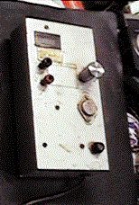
last weekend , when I arranged the stock room , I discovered my little
power supply. I made it , when I was 13 years old. I made many small projects
with that power supply on my young age. For the beginner of hand mader
, I will show you this power supply. See the circuit! Small power transformer
supplies 9V AC. Silicon diode passes through only plus side of AC. The
1000 micro farad capacitor stocks the electron. It becomes 12V DC. But
this power supply includes many ripple on this point. If I used such a
power supply, I could hear many hums from our radio. Ripple filter circuit
made by two transistors reject the ripple. The another 1000 micro farad
capacitor reject ripple again. A small meter indicates the voltage output.
I will explain about the movement of the ripple filter.
I define some symbols as follows.
Ve: Voltage between A point and E point=voltage drop of 500 ohm resister
Vo: Voltage of C point = outpot voltage
Vb: Voltage between B point and E point
n: radius of the variohm ( bigger than 0, smaller than 1)
The LED's voltage drop becomes 2V in any way. Therefore the next expression
is known.
Ve=Vo-2 ******(1)
The base oftransistor's voltage drop becomes 0.6V in any way. Therefore
the next expression is known.
Vb=Ve+0.6 ******(2)
The variohms voltage drop becomes porposional to the radius of it's shaft.
Therefore the next expression is known.
Vb=n*Vo *******(3)
Input (2) to (3)
Ve+0.6=n*Vo ****(4)
Input (4) to (1)
Vo-2+0.6=n*Vo
Vo-1.4=n*Vo
(1-n) Vo= 1.4
V0=1.4/(1-n) ***(5)
From expression (5) , I know as follws.
1. When I turn the variohm to the ground side, n becomes 0. Therefore Vo=1.4
2.When I turns the variohm to the center of it's radius, n becomes 0.5.
Then V0=2.8V
2.When I turns the variohm to the C point of the figure , n becomes 1.
Then V0 becomes infinite. But as actual, this condition means the perfect
ON of the NPN transistor. Therefore the circuit can not act as effective
filter any more. The actual maximum output voltage of this circuit is about
10V.
I used small power transformer . It is smaller than my fist. Therefore
the maximum current output of this machine is only 100mA. I used the aluminium
case for the heat sink of the NPN power transistor. If you want to make
more powerful power supply, you must use more big transformer and more
big heat sink.(The power transistor of this gear 2SC126 was power germanium
transistor.)

この前の週末に,納戸を整理していたときに,小さな電源器を発見しました.13
才だったときに,作ったものです.私は,その頃、その電源で多くの実験的製作をしました.初心者のために,この電源を紹介します.回路図を見て下さい!
小さい電源変圧器は,9V
の交流を供給します.シリコンダイオードは,交流のプラス側のみを通過させます.1000マイクロファラッドコンデンサーは,電子をため込みます.それ
は,12V
DC
になります.しかし,この電源は,このポイントで多くさざ波(リプル)を含みます.もしこのような電源をラジオの電源に使ったら,ラジオのスピーカーから
ブンブンいう音を聞くことができたでしょう.2個のトランジスターによって作られたフィルター回路が,さざ波(リプル)を押さえます.別の1000マイク
ロファラッドコンデンサーが,もう1度さざ波(リプル)を平滑します.小さいメーターは,出力電圧を示します.< BR >
さざ波フィルターの動きについて詳しく説明します.< BR >以下のようにいくつかのシンボルを定義します.
Ve: A−E間の電圧:500オームの抵抗の電圧降下
Vo: C点の電圧:出力電圧
Vb: B−E間の電圧
n: ボリュームの回転角度(nは0以上1以下)
LEDの電圧降下は2Vと決まっています。それで下記の式が判ります。
Ve=Vo-2 ******(1)
トランジスターのベースの電圧降下は0.6Vと決まっています。それで下記の式が判ります。
Vb=Ve+0.6 ******(2)
ボリュームの電圧降下はシャフトの回転に比例します。それで下記の式が判ります。
Vb=n*Vo *******(3)
(2) を(3)に代入して
Ve+0.6=n*Vo ****(4)
(4) を(1)に代入して
Vo-2+0.6=n*Vo
Vo-1.4=n*Vo
(1-n) Vo= 1.4
V0=1.4/(1-n) ***(5)
(5) 式より.
1.接地側にバリオームを回転するときには,nは0です。それゆえに Vo = 1.4になります。
2.ボリュームの軸を真ん中回転すると,n は,0.5. になります.その時出力電圧は、V0
= 2.8V。
3.図のC ポイントにバリオームを回転すると,n は,1 になります.その時のV0
は計算上,無限になります.しかし実際には,この状況は,NPN
トランジスターのパーフェクトなON状態を意味します.それゆえに,サーキットは,この時には効果的なリプルフィルターの役をつとめることができません.
そういった訳で、このサーキットの実際の最大出力ボルト数は,10Vです.
私は,小さい電源変圧器を使いました.それは,私のげんこつより小さい物です.それで,この電源器の最大の電流出力は,たった100mA
です.私は,NPN
パワートランジスターのヒートシンクとしてアルミニウムのシャーシケースを使いました.もし,より強力な電源が欲しければ,より大きい変圧器,およびより
大きいヒートシンクを使わなくてはいけません.(ちなみに2SC126はゲルマニウムパワートランジスターです)
back to index

 On
last weekend , when I arranged the stock room , I discovered my little
power supply. I made it , when I was 13 years old. I made many small projects
with that power supply on my young age. For the beginner of hand mader
, I will show you this power supply. See the circuit! Small power transformer
supplies 9V AC. Silicon diode passes through only plus side of AC. The
1000 micro farad capacitor stocks the electron. It becomes 12V DC. But
this power supply includes many ripple on this point. If I used such a
power supply, I could hear many hums from our radio. Ripple filter circuit
made by two transistors reject the ripple. The another 1000 micro farad
capacitor reject ripple again. A small meter indicates the voltage output.