COLLECTED BY
Organization:
Internet Archive
The Internet Archive discovers and captures web pages through many different web crawls.
At any given time several distinct crawls are running, some for months, and some every day or longer.
View the web archive through the
Wayback Machine.
Wide17 was seeded with the "Total Domains" list of 256,796,456 URLs provided by Domains Index on June 26th, and crawled with max-hops set to "3" and de-duplication set "on".
TIMESTAMPS
Simple television receiver.. ..tvphk.gif
 When I made FM radio, I could hear the voice signal of first channel of
TV. On the frequency slightly lower than that, I could hear the noisy signal
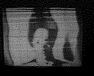
of picture of TV. My oscilloscope has Z input. It can display black and
white. I made the simple TV receiver. It displays the picture on my oscilloscope.
When I made FM radio, I could hear the voice signal of first channel of
TV. On the frequency slightly lower than that, I could hear the noisy signal
of picture of TV. My oscilloscope has Z input. It can display black and
white. I made the simple TV receiver. It displays the picture on my oscilloscope.
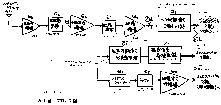
See fig 1! The signal (comming from the antenna) is amplified and detected.
It has the same circuit as a FM radio. But detector of it is amplitude
modulation detector. This radio do not have tune control. This machine
is able to receiv only the first channel. Receiving frequency is tuned
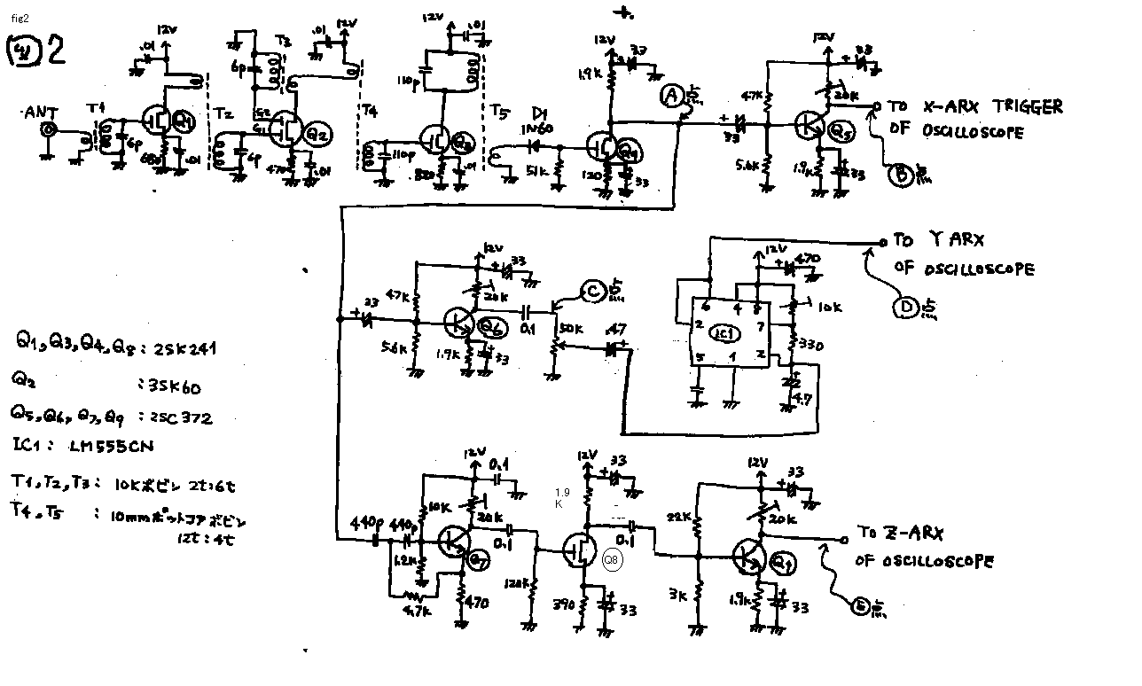
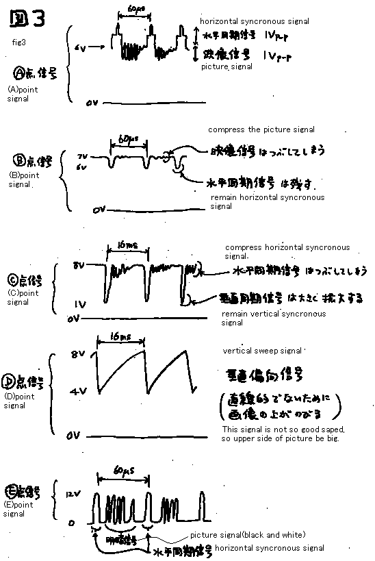
by core of T3. On the (A) point of fig2, I can watch the TV signal indicated
on the textbook. See fig 3! I show you the (A) point signal. (A) point
signal includes picture signal and horizontal synchronous signal and vertical
synchronous signal. Each signals are separated by the signal separator.
The famous oscillator IC (555) products the vertical sweep signal. And
it is synchronized by the separated synchronous trigger signal. Z input
of oscilloscope indicates only black or white. It can not display the gray.
It is TTL level input. Therefore the picture on the oscilloscope is only
yes or no. It can indicates only the outline of the picture. The Brown
tube of oscilloscope is not so bright as that of sold TV set. So I must
look it on the dark room.
I could enjoy to make this machine. If you are tired to make radios, make
TV!
Discription add on 10 Dec 98
Iliyan send the following E-mail. 10Dec98
I also made oscilloscope TV like you, but I used 4 resistor (1k,2k,4k,8k)
based DAC to modulate the beam - I mean pulse modulation for 16 shades
of gray intensity. It was disappointing, because the brightness of the
oscilloscope tube is not good to watch during the day! What do you think
about my projects? If you want to make them, you can also put them on your
home-page - I will be very happy! As I said, it was almost 20 years ago,
when I did it, so I do not have the original diagrams. The three major
components were CMOS Hexadecimal Buffered Counter with build-in clock (500khz),
4 x resistors connected to buffers, and Voltage Comparator. The principal
was very easy - counter starts counting clock impulses and as soon as the
voltage coming from the receiver is equal to the voltage, produced by the
resistors, comparator sends reset to buffers, and everything starts again
from the beginning. The output of the counter was also fed to the PCM modulator
of the Z input of my oscilloscope.
簡単なテレビ受像機(じゅぞうきと読んでください)
FMラジオを作っていたら,FM周波数の上のほうでテレビの一番下の
チャンネル(1ch)の音声信号を聞くことができました.そして、それよりわずかに低い周波数で,テレビの画面の信号が、ブーブーとうるさく聞こえて来ま
した.一方、私のオシロスコープは,Z入力を持っています.それは,黒と白を表示することができます.そこで、私は,シンプルなテレビ受信機を作ってみま
した.それは,私のオシロスコープの画面にテレビの絵を表示します.
図1 を見て下さい!
空中線からの信号は,増幅して,検波されます.この辺の回路は,FMラジオと同じです.ただ,その検波器は,AM検波器です.このラジオは受信周波数が固
定です.これは,第一チャンネルのみを受信出来ます.T3
のコアの調節で受信周波数を調整してNHK1チャンネルに同調します.図2の(A)ポイントには,テレビの教科書で示された様な画像信号を見ることができ
ました.図3
を見て下さい! (A )
ポイントの信号を示します.この信号は,画像信号,および水平同期信号,および垂直同期信号を含みます.それぞれの信号は,信号分離機(シグナルセパレー
ター)によって分離されます.有名なオシレーターIC
( 555
)が垂直のスイープ信号を作ります.そして,その垂直スイープ信号は,映像信号から分離された同期信号によって同期がとられています.オシロスコープのZ
入力は,単に黒,あるいは白の2値を示します.それは,グレー(灰色)を表示することができません.それは,TTL
レベル入力です.それで、オシロスコープの絵は,単にオンオフです
.それゆえ、この機械は,絵のアウトラインだけを示します.オシロスコープのブラウン管は,テレビのそれほど明るくありません.したがって,私は,暗がり
の部屋でそれを見なくてはいけません.
私は,このマシンを作る事を,楽しむことができました.もし,ラジオを作るのに飽きたら,テレビを作ってみて下さい.
記述追加12DEC98****
南アフリカのイリアンさんは、20年前に同じような物を作ったそうです。メールをくださいました。さらに、氏は、パルスモジュレーションをかけて、色の濃さを16段階に表示させたが、とても昼間は、見えなかったそうです。お試しあれ、との事。
tv1.gif
tv2.gif
tv3.gif
back to index
