COLLECTED BY
Organization:
Internet Archive
The Internet Archive discovers and captures web pages through many different web crawls.
At any given time several distinct crawls are running, some for months, and some every day or longer.
View the web archive through the
Wayback Machine.
Web wide crawl number 16
The seed list for
Wide00016 was made from the join of the top 1 million domains from CISCO
and the top 1 million domains from Alexa.
TIMESTAMPS
UHF signal-generator
One day, as a next step of my hand make
activity, I decided to make 430MHz transceiver. 430MHz transceiver includes
some 430MHz amplifier in it*s receiving front end and it*s transmitting final.
To tune these amplifier and band pass filter, I need UHF signal generator.
Therefore I went to the electric shops on the Tokyo (AKIHABARA), and I asked
the merchants in the store to sell me a cheap-UHF-signal-oscillator. But the
merchant told me that he has no cheap UHF-signal-oscillator, because UHF signal
generator is only professional usage. I understood that I have no way than to
make it by myself.
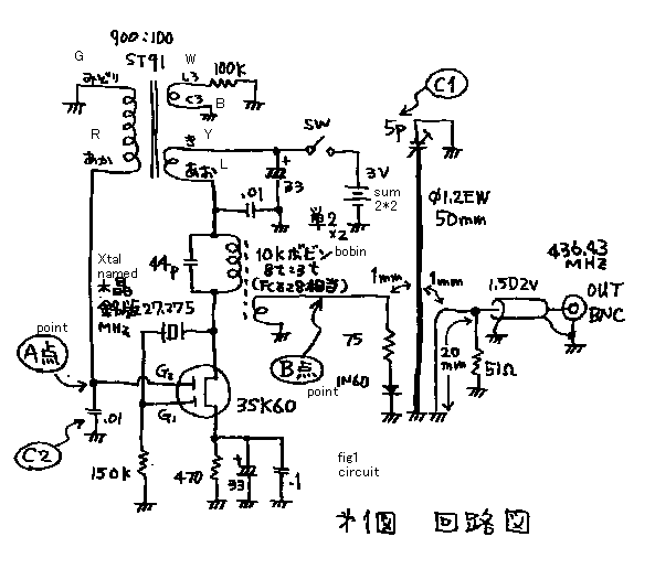
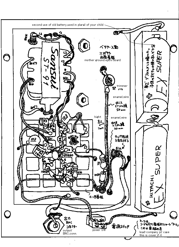
See fig 1. Double gate FET oscillate 27MHz signal by the crystal connected on
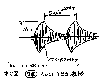
G1 of it. By the way, besides, double gate FET oscillate 200Hz signal by the
reaction transformer connected on G2 of it. Please see the output-signal of the
oscillator (B point) indicated on fig 2. And after that, the signal is
multiplied sixteen times by diode multiplier. Then, I can get 436MHz
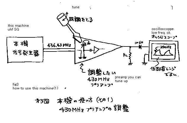
AM-modulated-signal at last. My original usage of this machine is indicated on
fig 3. I have no material to observe the UHF signal directly. So I shall
observe the signal by detecting with 1N60 connecting soon after the opposite
amplifier. With such a poor system, I can tune the patting capacitor of the filter.
I can make it sure about the action of the 430MHz amplifier. If amplifier has a
self oscillation, the view of the wave on oscilloscope may be different from
the figure in FIG2 and becomes some type of bad shape. I can know absolute gain
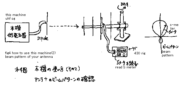
of the amplifier. Second usage is indicated on fig 4. I can make the
beam-pattern-figure of my antenna by this machine and 430-rig.
極超短波シグナル- ジェネレータ
極超短波シグナル- ジェネレータ
ある日,私は,430MHz
トランシーバーを作ろうと思いました。トランシーバーには受信部にしろ昇進部にしろ、増幅器や共振機が要りますが、その調整の為には430MHzのシグナ
ルジェネレーターがぜひ必要だと思いました。それで,秋葉原に行き,安価な極超短波シグナルオシレーター探しましたが,どこにもありませんでした。無い物
は作るよりしょうがありません。用途は限られますが、一応430MHzのアンプにさえ使えれば良いという割り切りで作ってみました。図1をご覧下さい.
回路の働きを説明します。デュアルゲートFETのG1に水晶をつないで、27MHzを発振します。また、一方、同じFETのG2に、ドレインからトランス
で正帰還をかけて、帰還発振器を組み,200Hzの可聴信号を発振させます。この信号で27MHzの信号は振幅変調される結果となります。デュアルゲート
FTEオシレーターの出力信号をそのドレイからコイルを通じて取り出し,ダイオード逓倍器によって16逓倍されます。これで,振幅変調された436MHz
信号を発生することができます。このマシンの元来の使い方を図3に示します。430MHzのUHFでは私のオシロスコープではもちろん計測が不可能なの
で、ダイオードで検波して観察する様にします。こんな、間接的な方法でも、たとえば、もし増幅器が,セルフな発振をしていれば,オシロスコープの観察波形
が,もとの200Hzの変調波形で無く、ほかの悪い形で現れますので、増幅しているかどうかの確認はできます。また同時に,増幅器のゲインもおおよそ計る
ことができます。同調のピークも解ります。第2の使い方を図4で示します。この機械と430のリグを使って,アンテナのビームパターンを測定することがで
きます。普通の送信
機の出力では、このような実験は何キロもはなれなければできませんが、この機械の場合には出力電力が小さい事が幸いして、数メートルでこの実験ができま
す。
uhfsg1.gif
uhfsg2.gif
uhfsg3.gif
uhfsg4.gif
uhfsg5.gif
return to index


