Original idea and implementation by sv3ora

Electromechanical
"magic eye" display
Original idea and implementation by sv3ora
Magic eye indicators always fascinated people. But a magic eye tube may not always be available when you want it, plus some time in the future good condition eye tubes will be rare. Not always that but the high voltages involved, make this a project unsuitable for the inexperienced. Also, magic eye tubes come in predefined sizes/shapes. Therefore I decided to reproduce a magic eye in electromechanical means. I first saw this idea on this website but it included lots of mechanical parts and certainly it was not a simple project. Therefore I experimented on different ideas of how to make the mechanical construction as easy as possible. I also created my completely own schematic, the first version of which I present below. Later on in this article, you will find more elaborate updates of the magic eye display.
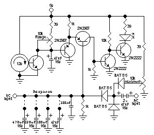
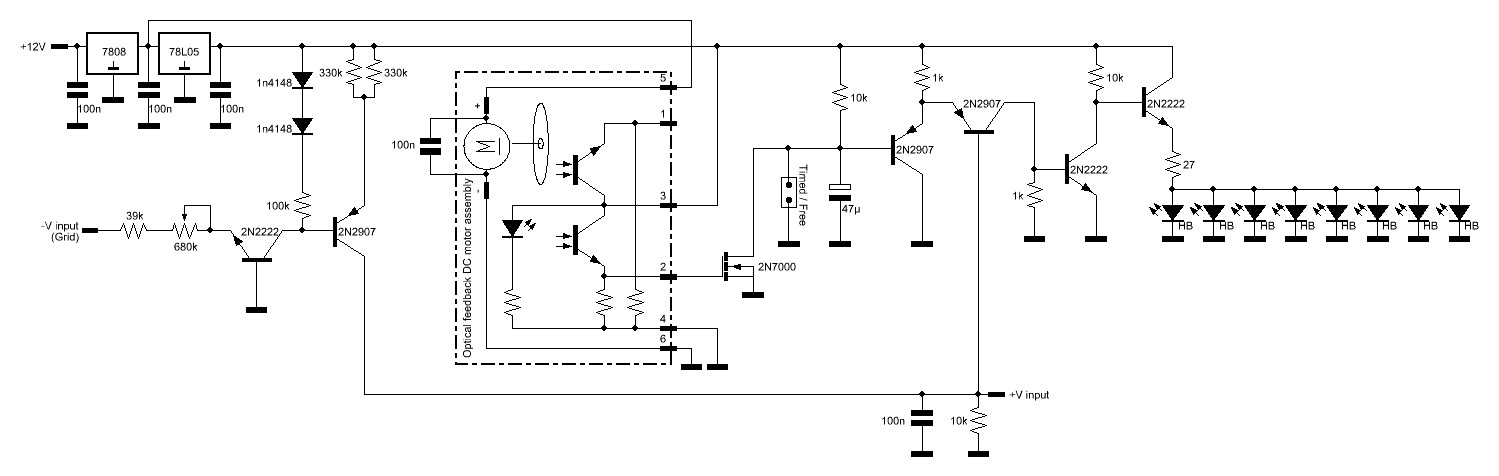
My initial circuit uses only a few discrete components. The two 2n2907 transistors, form a simple comparator and the two 2n2222 transistors a schmitt trigger and led driver. In my circuit, the range of voltage which the display shows can be adjusted (display deflection) from about 100mV to about 5V. There is also a preset minimum control, so that the display stays on (but at minimum deflection) even on the minimum voltage level.
Because
I wanted to use this indicator as a useful general purpose measurement
display device, I included two imputs. The one at the left, accepts DC
(100mV-5V) and the one at the right accepts audio or RF AC (0Hz-30MHz
tested ok, but it can go much higher), which is detected and converted
to DC to drive the comparator. Because the indicator is to be used in
different applications requiring different responce times of the
display, I included four electrolytic capacitors at the input, that can
be switched in a decade capacitor configuration (one at a time or in
combination), which slow down the response of the display accordingly.
The emectromechanical display is very fast, much faster than an analogue needle meter, so it is capable of displaying the peak power in SSB transmitters. It is also very accurate, the "beam" is straight line and not bended like in many magic eye tubes. Thus you can do actual measurements, by placing a scale on the perimeter of the "beam" of the indicator.
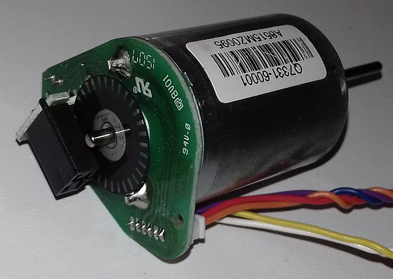
As
far as the mechanical construction concern, the first version of my
electromechanical magic eye indicator, has been built using a CPU
motor. These motors have 3 wires, two of them are the DC to the motor
and the third, is a feedback from the magnetic sensor inside the motor,
which is used to control the speed of the motor. These motors can be
almost noiseless when rotating, especially if you cut the fins, like I
did for this experiment. Here is a short animated gif of my first
version in operation.

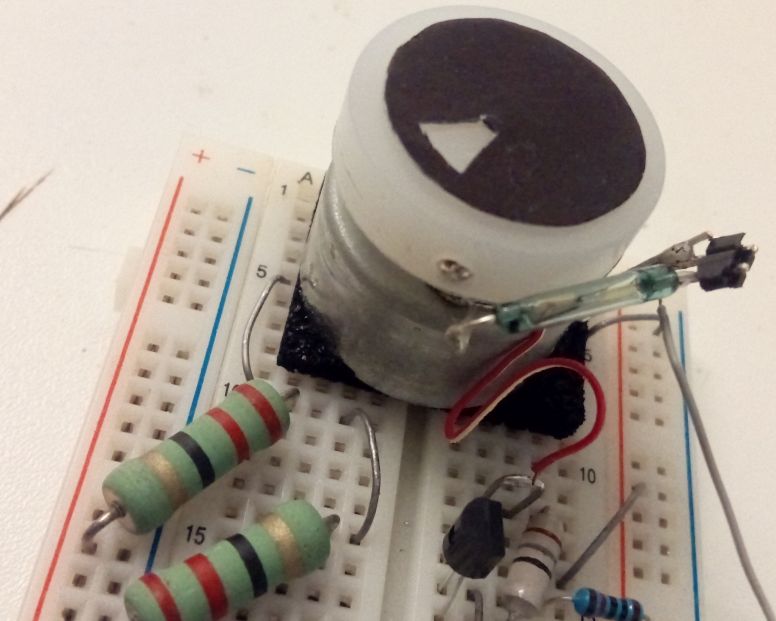
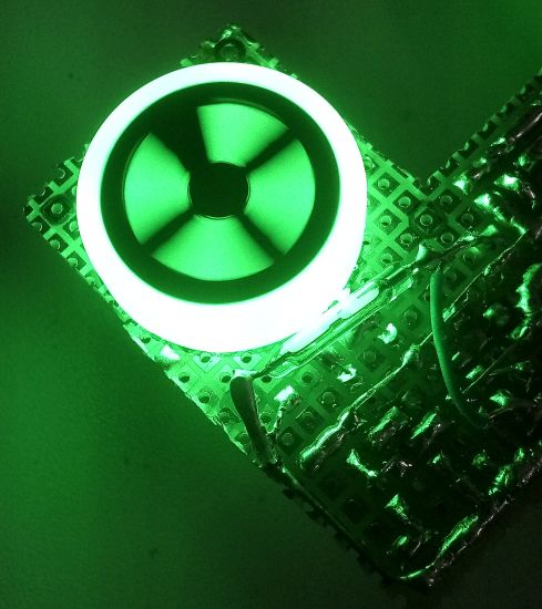
In this version, I greatly reduced the mechanical complexity, due to the CPU motor that contains all the parts inside. However, this can only lit from the front now, which raises another problem, glare. A LED must point to the front surface of the motor, and shine a target (yellow line) which in turn reflects the light. But to be successful, we must ensure a high contrast between the black area and the yellow line and glare is our enemy. I did different experiments, but the best results for this version of the indicator, were obtained by using a transparent lamination film and laminating a paper below it, where it was painted yellow. Then I painted the film top surface with thick black permanent marker. The led must point to the film from it's sides at an angle and not directly from it's top. This reduced glare to the minimum and gave a high contrast to the indicator as you see in the picture below.
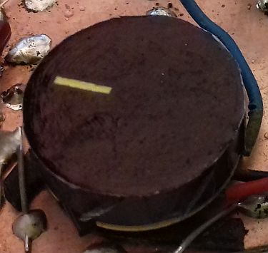
The result was good but not perfect. If you notice the picture above, the permanent marker (which dries really fast) have been kept long onto the film surface and dried. The second time the marker tip passed over the film to make a second layer, distorted the finish of the previously dried marker. These little distortions reduce contrast in a fast spinning disc.
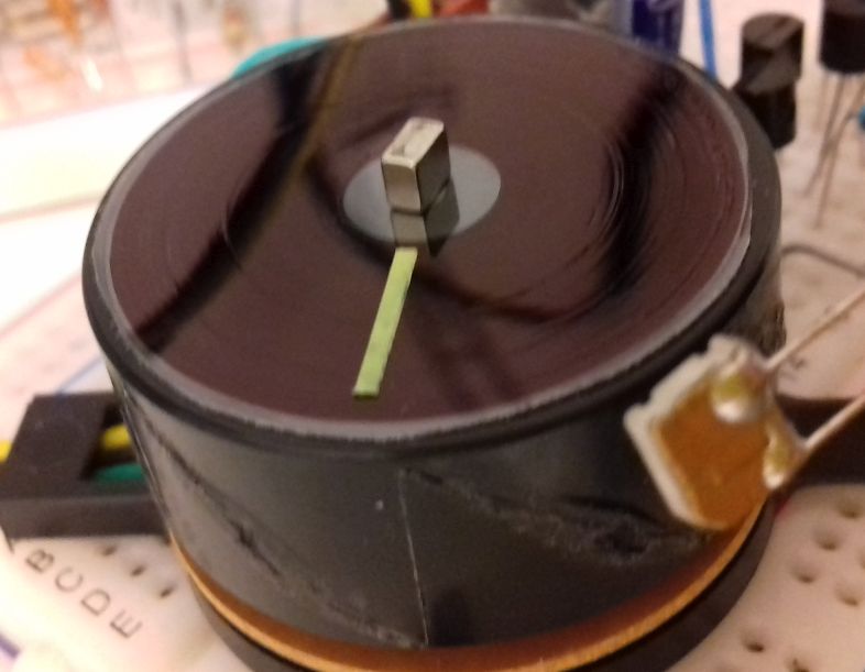
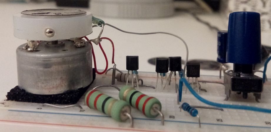
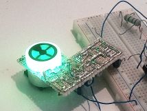
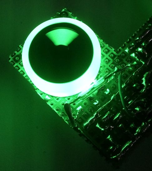
The picture above shows my second experiment. This time I used a larger diameter CPU motor and I did not laminate any paper. Instead I used the transparent film alone and I painted it at it's external surface with the same permanent marker. The way I painted it was, I clipped the film onto the motor shaft with a small magnet and I let the motor spin at low speed. Then I put the marker onto the surface of the film and like a gramophone, I scan through the film surface with the marker. This cave a much better finish. there are still some distortions but these are much much smaller now. Use the thickest marker you have to minimise these distortions. This time, I also cut a small piece from a luminescent green-yellow sticker I have found and I glued it onto the transparent film surface, to form the indicator.

The
animated gif above shows my second version. The shadow at the top is
caused by the large height magnet I used, but this was just for
demonstration purposes. The usage of the magnet allows for easier
alignment of the film. As a light source, I found white LEDs better,
but this depends on the luninescent indicator material. If you use a UV
LED, the glare is much reduced and the indicator shines bright. But for
eye safety reasons I did not use one. Because of the usage of a visible
LED, you have to make sure that if you enclose it into a box, the white
LED must not shine out of the box to your eyes, but only to the film
surface.
The
second version worked great and if you really do not want to mess up
with any mechanical parts, this is the way to go. However,
there are still things that can be improved if one wants a better
result. The glare, although minimized, can still be seen by looking at
the eye from an angle. The permanent marker drawn disc is something
that might not be very durable and it is affected by dirt and hands
fingerprints. Also, the usage of the CPU motor has a property that can
be thought as a disadvantage or not, depended on what you are trying to
do. These motors reset twice per revolution, so the eye pattern is
repeated giving two beams instead of one. Now, many magic eye tubes use
this two-beam pattern, so this can be considered as a more realistic
effect. However, this reduces the screen resolution to 180 degrees
instead of 360 degrees. Not only that, but the magnetic sensor inside
these motors causes the resolution to decrease even more and in fact
the usable pattern angle is a little more than 100 degrees.