A full-sized microcomputer
inside a keyboard
by SV3ORA
Introduction
I always wanted to have a compact computer that I could carry with me and that I could use it for all of my LAB projects. I have tried to build single board computers in the past, including the ZX80 and the Jupiter Ace. These computers are ok, but since they come from an era where microcontrollers were slow and expensive, they use discrete chips to do the job. As a result, they are bigger, heavier, more expensive and their characteristics are not so good as modern microcontrollers.
The idea of a simple single-chip useable computer inside a modern microcontroller was running into my mind for a long time, but since my assembly skills were not good enough, I waited for a person to release such a project. Eventually I found this wonderful project (translated local copy here and original DE texts here), which I decided to build. My goal was that everything should be simple and easy to make, so I have decided to build it using DIP chips, no SMD at all. An immediate modification I thought, was to build the computer inside the keyboard case, instead of carrying external cables. I hate external cables, even modern laptops require a hand case filled with the charger and various cables. This is not portable for me. To my taste, a computer should only have the minimum amount of required cables, even no cable at all, with the PSU attached inside it, if possible.
In this page, I
present some hints and tips to build your own computer from scratch. It
is basically a a description of the problems I have encountered when
building it, so you do not have to reinvent the wheel.
Building the basic hardware
To build the project, first please read completely the translated description in the zip file. There is no need to repeat these information here, it is already well documented. In this page I will guide you through my modifications and the way I built the project.
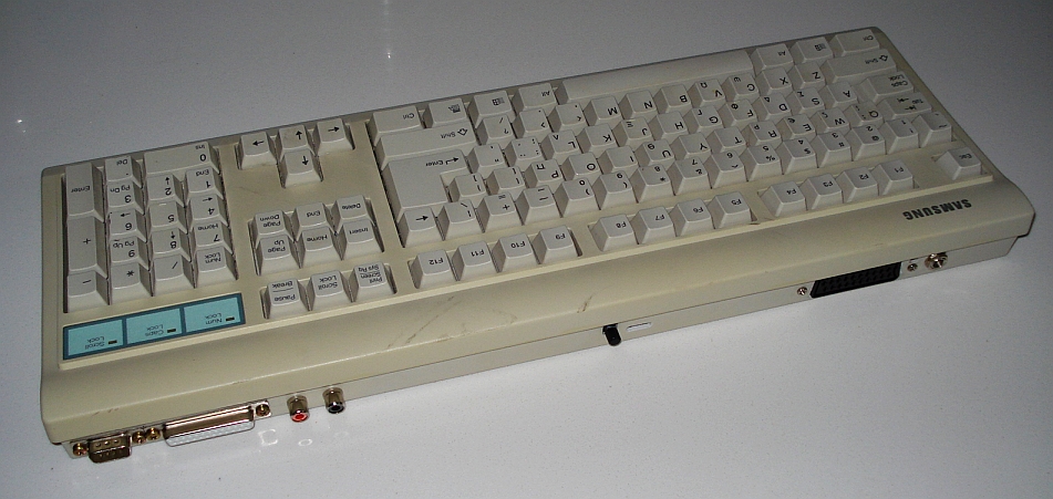
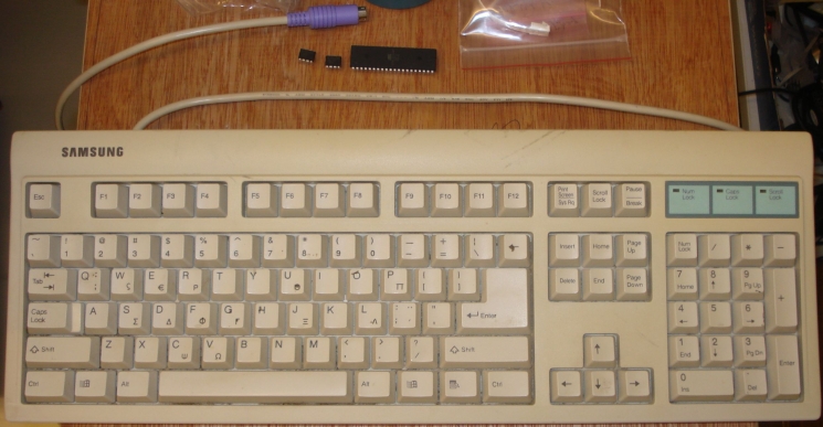
I found an old full-sized, keyboard. I like standard keyboards and I avoid keyboards that have these multimedia buttons, these are just nonsense and mostly waste of computer resources. A slim keyboard is not suitable for this project, use a standard size PS2 keyboard, since it is thicker, and it has much more free space inside, for the computer to be installed. Try to find a keyboard where it's top side is bigger, to allow for more free space (it is the area where the Samsung logo is printed in my case).
After opening the keyboard, the first thing you need to do is to locate the PS2 cable, which should be somehow attached to the case and detach it.
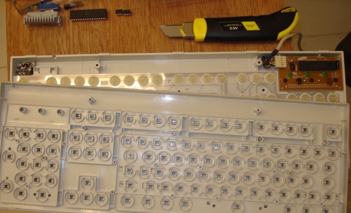
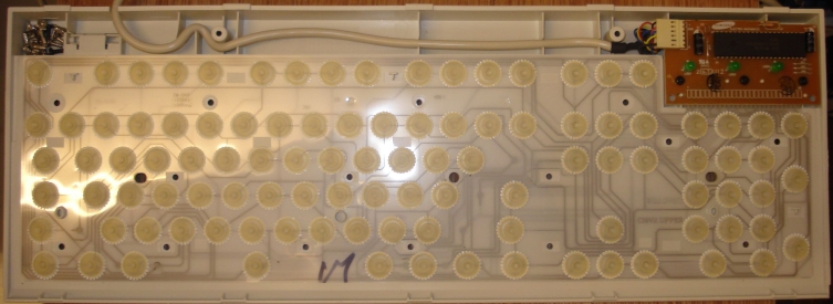
To allow for more free space, you may need to cut a few plastic pieces from inside. In my case, these were a few vertical pieces of plastic that were used to hold the PS2 cable in place. Cut these pieces from both the bottom and the top side of the keyboard. This leaves plenty of space for the microcontroller, the rest of the components and the connectors to be installed.
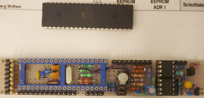
To built
the computer as small as possible and to be easier to modify it later
on, I made it on a proto board, cut in size so that it can be fit
inside the keyboard. Note that some components wave been soldered
inside the microcontroller socket, to save space.
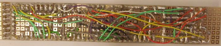
The bottom of the proto board is quite messy, but not so messy
so that it would be difficult to debug. Also, note that the PS2 connector in the
schematic, is shown as it is seen from the front of a female PS2 connector, just
like if you were looking at the PS2 port of your computer, with the keyboard
cable taken out. This is important, to make the right connections, since
reversing VCC and ground will result in a damage of your keyboard controller.
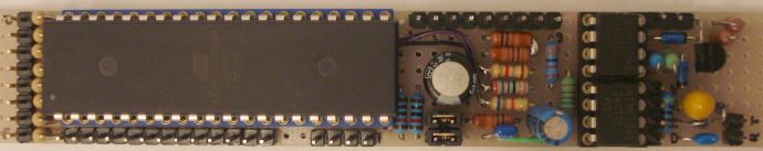
This is the almost finished computer board. Pins have been installed in all external port connections. I found this way easier, in order to fit the external connectors and for debugging purposes. I wanted to install all the available connectors, but if you do not, connect only the desired connectors to the appropriate pins.
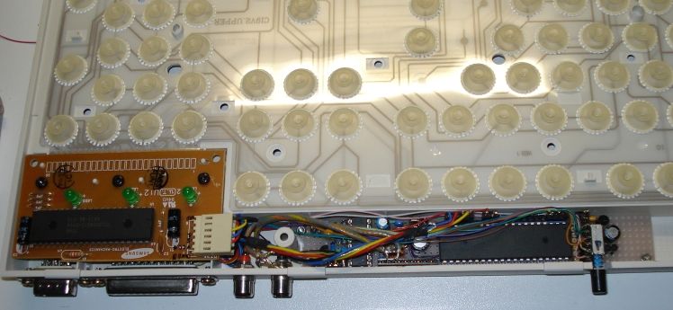
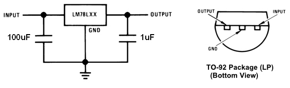
The board is installed inside the keyboard case and connected with all the desired mounted connectors. There is also an ON/OFF switch installed, as well as a 78L05 regulator to regulate the power to the board. It's schematic is shown below.
Programming the microcontroller
Programming of the microcontroller is a bit tricky.
Do not expect the computer to work if you just write the HEX into the
microcontroller without setting any fuses. All you will get, will be
random TV lines and a continuous sound tone. To do so, the programming software must support
altering fuses settings. For this project, the fuse settings can be
found in the "liesmich" file inside the binary package. The fuses are:
ATMega 644:
------------
LOW 0xe6
HIGH 0xd1
EXT 0xfc
To make it easier for the homebuilder to build this project, I include
the exact procedure and programmer I have used to program the
microcontroller.
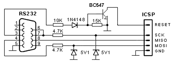
This
is a variation of a very simple programmer, altered especially for this
project. Do not use this to program other projects. You must program
the microcontroller by leaving it connected onto the computer board
(ICSP). You may notice that there is no external VCC neither a resistor
from VCC to RESET. This is included in the computer board schematic
instead. Obviously, you must apply VCC to the computer board, prior to
programming.
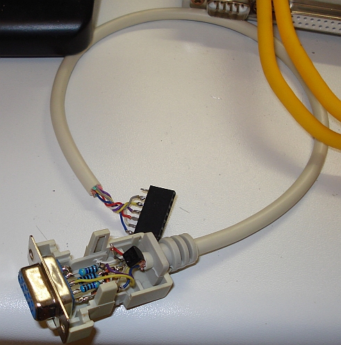
The programmer can be easily built in air style technique inside a serial connector, as shown in picture above.
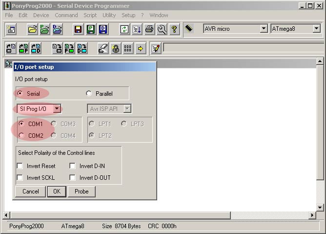
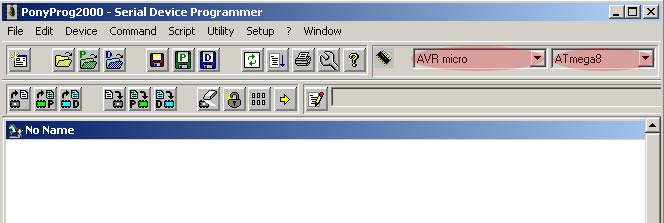
The software used for programming and setting the fuses, is PonyProg. After the installation, the first thing you will need to do is configure PonyProg to work with the AVR Programmer. Connect the programmer to the PC and go to "Setup" menu and select "Interface Setup". The following window will be shown and highlighted areas show you exactly which options should be selected.
Next, select "Setup" and "Calibration", to calibrate the software.
In the next step select "AVR micro" and your microcontroller type that you will be programming (ex. ATmega644).
At
this point PonyProg configuration is complete and you may open the hex
program with which AVR microcontroller will be flashed. Go to "File"
menu, select "Open Program (FLASH) File ...", and point to the hex file
to open it up. The relevant hex file is included into the translated local copy file
or look at the author's website for more recent updates. You should see
hex numbers apear in the program display, when the program is loaded.
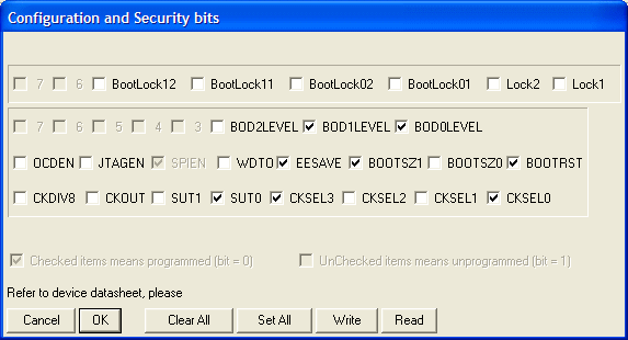
Next
select "Command" and then "Security and configuration bits". Make the
relevant settings are as shown in the window below and click "OK".
Then, in the main program window select "Command" and then "Write all", to program the microcontroller. Ignore any warnings or verification errors that might appear during programming. After programming, remove the ICSP connector and test to see if your computer boots up ok.
Loading programs to the AVR
Loading programs to the AVR and from the AVR to the PC has been proven tricky as well, therefore I present you the exact procedure for successful loading and PC communication.
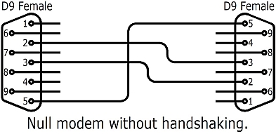
At first, a suitable serial cable must be made using the schematic below. Connect this cable to the AVR and the PC serial ports.
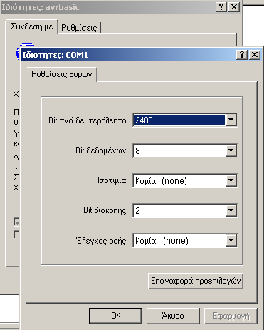
Next, open HyperTerminal program in windows. Set the HyperTerminal com port settings as shown below. Then save and connect.
Next go to the CONFIG icon on the AVR screen and make the next settings:
Serial speed: 2400 Bps
Serial In/Out: simple
Serial Input: PD1
Save the settings and the AVR will reboot.
The
first program you need to load, is the kbd_us.bin (found inside the
package) in order to set the AVR keyboard to US layout. Go to the
HyperTerminal and click transfer > send file. Select Xmodem protocol
and the kbd_us.bin file and then click Send. On the AVR, mark the program number on the AVR screen and
press CTRL+F3
to start the transfer. Once the program transfer has been completed,
press F4 on the AVR to run the program. Once the program has been run,
press CTRL+C and ESC to terminate it. The new layout is now set and you
may delete the program to save space by pressing CTRL+F4 on the AVR.
From now on, every time you reboot the AVR, the default layout will be
the US.
So far I have written about sending binary files to the AVR. If a text program listing is to be sent to the AVR, mark the program number on the AVR screen and press F1 to edit it. Then press CTRL+F3 to get into receive mode. On the HyperTerminal click transfer > send text file. Then select the text file listing to be sent.
Note that the programs examples listings presented on the translated package may contain errors due to the automatic translation, so please refer to the original article for the correct listings.
Program types
The microcontroller can run different program types. It can run native AVR programs and in emulation mode it can run AVR chipbasic2 programs, Chip8 programs as well as 8080 programs. Aside from the AVR native and Chipbasic2 programs that exist inside the software package, click here to download many chip8 programs that can run on this system. These are not included in the original package. Note that you cannot download any Chip8 program from the internet and run it directly on the microcomputer, as it has to be first converted into a special format for the micro to be able to run. There is a program that allows you to do so inside the TOOLS folder of the additional package. I have already converted every Chip8 program inside this package, so you do not need to do it by yourself, just load the programs to the micro to run them.
To run Chip8 programs, first Chip8 emulator has to be loaded into position P2 on the microcomputer screen and the library XMEM IRAM2 must be loaded into position P8. Run the Chip8 emulator and when the emulator is running, press F3 to load any Chip8 program from the DFLASH into it.
Optional extensions
DFLASH memory
In the original article, you will find the schematic of adding a DFLASH to store many additional programs for the microcomputer. This very usefull addition, allows you to store up to 255 programs inside the flash chip, that are available for instant loading into one of the eight positions (P1-P8) in the main microcomputer screen. It also allows you to save any program loaded or written in these positions, to the flash chip. The DFLASH works similarly to the HDD of a PC, allowing you only to load and store programs to it, whereas positions P1-P8 work as the main edit and run area for your programs. If you want to run a program that is stored into DFLASH, you first have to load it in one of the eight positions (P1-P8). Also, note that the Chip8 emulator, allows only to load programs from the DFLASH.
The author has used an external removable plug-in board for the DFLASH, in a similar way like a USB stick is used. I found 255 programs to be more than enough for my needs, so I permanently installed the DFLASH inside the computer. This way, does not allow you to exchange DFLASHes, but it is convenient in the sense that you do not have to carry an external DFLASH with you all the time. As I said, 255 programs storage is usually more than enough.
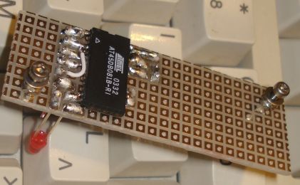
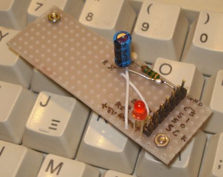
Although the flash chip is SMD, most of the pins are not used. To be easier for you to solder, I show you how to cut the unused pins and bend some of the used ones, so that the pins are spaced far apart for you to solder on a proto board. The LED used, has an interesting feature. When any read or write activity is done on the DFLASH, the led brightness changes and it behaves both as an ON indicator, as well as an DFLASH activity indicator. I drilled a small hole into the keyboard and put the LED into it, so that it can be used as ON indicator for the computer, as well as a DFLASH activity indicator.
The
flash chip is soldered directly on the copper side of the proto board.
For the connections of the chip, to the microcontroller (usually-free)
ICSP port, I used the same pin-row connector scheme like before. This
way, whenever I need to re-program the microcontroller, I plug-out the
DFLASH connector and plug-in the programmer to the ICSP. This procedure
ensures that the DFLASH will be always disconnected when programming
the microcontroller.
RGB to composite video encoder
Color is nice, but unfortunately, the scart color did not work at any of my TV sets. I checked the circuit for errors many times and I could not spot any of them. Thus, I decided to add an RGB to composite video encoder, for color graphics. The AD724 was the most simple solution. I built the circuit in page 10 of the datasheet, but I did not include the S-video and the RGB buffer opamps, as I only needed a composite video output signal. The circuit worked at once, so it made me confident that my implementation was right and some kind of incompatibility on the Greek TV scart might have been the problem.
To be continued...