What is PIC?
PIC is a family of RISC (Reduced Instruction Set Computer) microcontrollers made by Microchip Technology, derived from the PIC1650 originally developed by General Instrument's Microelectronics Division. Microchip Technology does not use PIC as an acronym; in fact the brand name is PICmicro.
What the name PIC stands for and who actually came up with the first PIC is an open dispute, some think it is an acronym of Peripheral Interface Controller. However, I have been looking thru out the net and found that original General Instruments' acronym for the PIC1650 was "Programmable Intelligent Computer". The original PIC was built to be used with GI's new 16-bit CPU, the CP1600. While generally a good CPU, the CP1600 had poor I/O performance, and the 8-bit PIC was developed in 1975 to improve performance of the overall system by offloading I/O tasks from the CPU. The PIC used simple microcode stored in ROM to perform its tasks, and although the term wasn't used at the time, it is a RISC design that runs one instruction per cycle (4 oscillator cycles).
Design of the PIC16x8x
PIC16CXX uses a Harvard architecture, with separate data and program storage. This allows faster access, as well as program and data to have different word width. Opcodes are 14 bits wide, versus data, which is 8-bit. The figure below is PIC16x8X block diagram showing ALU (Arithmetic Logic Unit) which is a general purpose arithmetic unit, memory, timers, oscillator in/out, master clear, 5-bit PORTA, 8-bit PORTB, voltages. Note the separate data, program, direct, indirect, and RAM address buses. Note also the 8-level 13-bit stack, the RAM file registers, and FSR register.
The ALU is a general purpose arithmetic unit. It performs arithmetic and Boolean functions between data in the working register and any register file. The ALU is 8-bits wide and capable of addition, subtraction, shift and logical operations. Unless otherwise mentioned, arithmetic operations are two’s complement in nature. In two-operand instructions, typically one operand is the working register (W register), and the other operand is a file register or an immediate constant. In single operand instructions, the operand is either the W register or a file register.
The W register is an 8-bit working register used for ALU operations. It is not an addressable register. Depending on the instruction executed, the ALU may affect the values of the Carry (C), Digit Carry (DC), and Zero (Z) bits in the STATUS register. The C and DC bits operate as a borrow and digit borrow out bit, respectively, in subtraction.
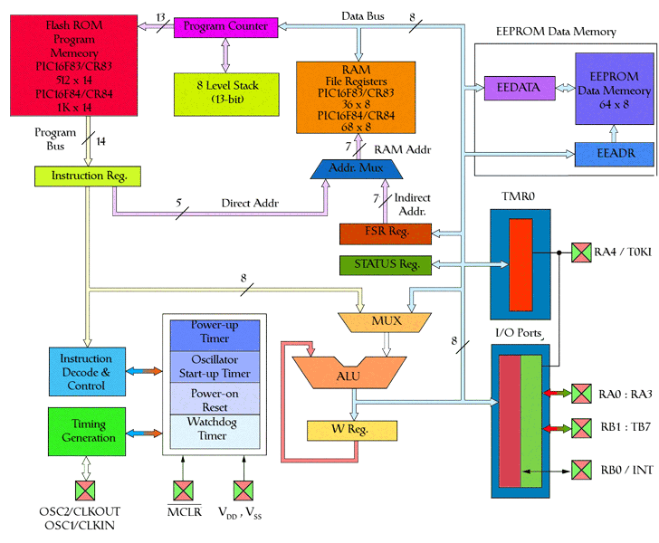
PIC 16x8x Block Diagram
The PIC16XXX devices have only 35 instructions, whereas the PIC17XXX devices have only 58 instructions. There is a substantial amount of program code compatibility amongst different devices in the PIC family. A program written for one PIC device can easily be assembled and used in another device type with a minimum number of modifications.
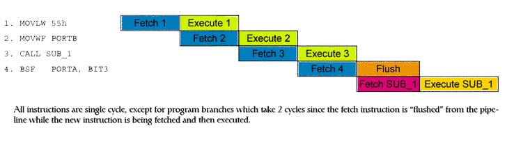
Instruction Pipeline Flow
The PIC family are fully static devices, meaning that they preserve the contents of their registers when the clock frequency is reduced to zero. In PIC microcontrollers, each instruction takes four clock periods to execute.
Instructions are pipelined in a way where one instruction is executing, another is being fetched from memory so that the instruction fetch/execution cycle takes only one clock cycle.
If a 1MHz clock frequency is used, the corresponding clock period is 1µsec, so each instruction will take 4µsec this time is called the instruction cycle time ti. The fastest devices in the PIC family can operate at clock frequencies up to 33MHz, with corresponding instruction cycle times of 121nsec. Most instructions execute in one instruction cycle, but some require two cycles because they need to branch to some destination other than the next address in the PC. Instructions that need two cycles to execute are btfsc, btfss, call, decfsz, goto, incfsz, retfie, retlw and return.
Microchip characterises PIC microcontrollers according to their instruction word lengths. The low-end PICs, such as the eight pin 12C5XX series, have 12 bit word length instructions. The midrange PICs, such as the PIC16XXX, have 14 bit instructions and the high-end 17XXX PICs have 16 bit instructions. All PIC microcontrollers are, however, classified as eight bit microcontrollers as they all manipulate data in byte units on an eight bit wide data bus. A detailed knowledge or understanding of these concepts is not essential to actually use PIC microcontrollers; all that is needed is practice in writing programs and some experimentation with microcontroller circuits to gain experience.
PIC 16F84 Pin Diagram.
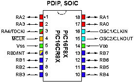
| Pin Name | DIP/SOIC Number | Description |
| OSC1/CLKIN | 16 | Oscillator crystal input/external clock source input. |
| OSC2/CLKOUT | 15 | Oscillator crystal output. Connects to crystal or resonator in crystal oscillator mode. In RC mode, OSC2 pin outputs CLKOUT which has 1/4 the frequency of OSC1, and denotes the instruction cycle rate. |
| MCLR | 4 |
Master clear (reset) input/programming voltage
input. This pin is an active low reset to the device. |
| RA0 | 17 | PORTA is a bi-directional I/O port. |
| RA1 | 18 | |
| RA2 | 1 | |
| RA3 | 2 | |
| RA4/T0CKI | 3 | This Pin can also be selected to be the clock input to the TMR0 timer/counter. |
| RB0/INT | 6 |
PORTB is a bi-directional I/O port. RB0/INT can also be selected as an external interrupt pin. |
| RB1 | 7 | |
| RB2 | 8 | |
| RB3 | 9 | |
| RB4 | 10 | |
| RB5 | 11 | |
| RB6 | 12 | |
| RB7 | 13 | |
| VSS | 5 | Ground reference for logic and I/O pins. |
| VDD | 14 | Positive supply for logic and I/O pins. |
Pinout Description
What dose the bar over
MCLR
mean: It means that this pin is active when it is connected to 0V rather than 5V