Square wave generator
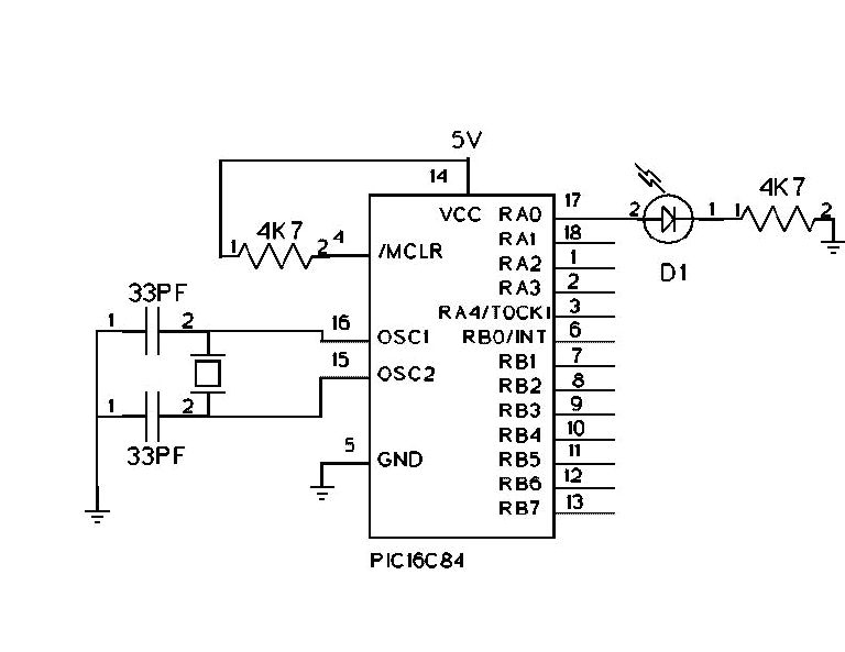
; Mark Crosbie  9/12/98  mark@mastincrosbie.com
; Scope test program. Flash an LED at a high frequency
; to observe changes.
;
;  The Program simply sets up Bit 0 of Port "A" to Output and then

;  loops, setting the value alternatively low and high
;
;  Hardware Notes:
;   Reset is tied through a 4.7K Resistor to Vcc and PWRT is Enabled
;   A 220 Ohm Resistor and LED is attached to PORTA.0 and Vcc

;
;	device	pic16c84

	include "p16c84.h"
   __CONFIG _CP_OFF & _WDT_OFF & _XT_OSC & _PWRTE_ON

;  Mainline of FlashFast

  org 0

  clrf   PORTA                  ;  Clear all the Bits in Port "a"

  clrf   STATUS
  bsf    STATUS, RP0            ;  Goto Bank 1 to set Port Direction
  bcf    TRISA, 0               ;  Set RA0 to Output
  bcf    STATUS, RP0            ;  Go back to Bank 0

Loop
  movlw 1                       ;  Turn on the LED on Port A

  movwf PORTA                   ;

  movlw 5
  call mdelay			; 5 uS delay

  movlw 0                       ;  Turn off the LED on Port A
  movwf PORTA                   ;

  movlw 5
  call mdelay			; 5uS delay


  goto Loop

; counter variables

CNT	dt	0
CNT1	dt	0
CNT2	dt	0
CNT3	dt	0
CNT4	dt	0

; delay for w uS. Set the w register to the desired delay value

MDELAY:
	MOVWF	CNT		;LOAD DELAY TIME

COUNT:	NOP			;TWO NO OPERATIONS
	NOP			;TO OBTAIN THE DELAY
	DECFSZ	CNT,1		;DECREMENT THE COUNTER
	GOTO	COUNT		;GOTO COUNT IF NOT FINNISHED
	RETURN

  end
Marker generator
;markrgen.asm - a program to generate 100, 50, 25, 10 and 5 Khz markers
;
; 10/23/99 Chuck Olson, WB9KZY
;
;       WHATDUZITDO?
;
; This program uses a 16F84 PIC microcontroller to generate accurate
;square waves at frequencies of 100, 50, 25, 10 and 5 KHz.  When the output
;is coupled via a very small value cap to a receiver, the odd and even
;harmonics of these markers can be heard all the way through to 30 MHz.
; The markers are selected via a momentary push button switch closure to
;ground on pin 1.  At powerup, the PIC will output a 100 KHz signal
;to pin 6.  If the momentary switch is pressed and released (PAR), the
;the output will change to 50 KHz - subsequent PARs will advance down
;to the 5 KHz marker and then wraparound back to the 100 KHz marker.
;
;If pin 2 is grounded, the marker will be gated (turned on and off at
;a regular interval).  The frequency of the gating will increase as
;the user changes the markers to allow easy identification of the marker.
;The 100 KHz marker has a slow on/off tone while the 5 KHz marker will
;have a very rapid buzz.
;
;If pin 18 is grounded, the duty cycle will change from the normal 50%
;square wave to a 10% square wave.  The idea was to even out the even
;and odd harmonic amplitudes, however, this isn't really accomplished
;but decided to leave it in anyway.  It may (depending on the frequency)
;increase the amplitude of the even harmonics slightly.
;
;Programming notes:
;
; The program is basically a timed loop.  The 100 KHz loop is the
;tightest, executing in 10 microseconds (us).  With a 4 MHz clock the
;PIC executes all instructions in either 1 or 2 us.  This makes it quite
;easy to simply count the cycles of the loop to allow for exactly the
;correct time delay - the PIC output is then set to a 1 or 0 as needed.
;Seperate loops are used for all 5 markers and duty cycles - there are
;undoubtedly more efficient ways to do this, but this method does work.
;
;The gating of the markers is accomplished with the use of the watch dog
;timer (WDT) feature of the PIC.  The WDT is a seperate RC on-chip
;oscillator with a period of about 18 ms.  The prescaler is used to count
;an integer number of WDT periods - after the prescaler overflows, the
;chip is reset, then a matching period of silence is generated using a
;timed loop.  The loop to be executed is determined from the bits of
;the FSR register - the FSR register was used because it is left alone
;during a reset of the chip.
;
; Hardware notes:
;
; I built a prototype on perf board - I had a little trouble with
;adjusting the 4 MHz oscillator to be right on frequency - the value of
;the caps or something else may need to be changed - one of the
;two 33 pf caps connected to the crystal should be variable trimmer
;cap to allow this adjustment.  It should be possible to use an external
;4 MHz oscillator to drive pin 16 instead of using a crystal although
;I haven't actually tried this.
;
;  PIC pinout:
;
;pin    name    function/connection
;---    ----    -----------------------------------------------
;  1    ra2     marker select, pulled up to +5V with a 10K resistor
;  2    ra3     gate select, pulled up to +5V with a 10 k resistor
;  3    ra4     no connect
;  4    MCLR    pulled up to +5V with a 10K resistor
;  5    VSS     Ground
;  6    rb0     marker output
;  7    rb1     no connect
;  8    rb2     no connect
;  9    rb3     no connect
; 10    rb4     no connect
; 11    rb5     no connect
; 12    rb6     no connect
; 13    rb7     no connect
; 14    VDD     +5V
; 15    osc2    connected to one side of 4 MHz xtal, also 33 pf cap to gnd
; 16    osc1    connected to other side of 4 MHz crystal & 33 pf cap to gnd
; 17    ra0     no connect
; 18    ra1     duty cycle select, pulled up to +5V with a 10 k resistor


	LIST P=16F84, R=DEC
	INCLUDE "p16F84.inc"
	__FUSES _PWRTE_OFF & _CP_OFF & _WDT_ON & _XT_OSC

;constants
; bit definitions
freq    equ     d'173'   ;1/2 ms delay loop constant


;  bit usage in the register FSR   -   bit 0 = 1 -> 100 KHz
;                                      bit 1 = 1 ->  50 KHz
;                                      bit 2 = 1 ->  25 KHz
;                                      bit 3 = 1 ->  10 KHz
;                                      bit 4 = 1 ->   5 KHz


; memory locations
count   equ     0x0C    ;a delay loop counter variable
temp    equ     0x0D    ;used in the delay loops
temp2   equ     0x0E    ;used in the delay loops
temp3   equ     0x0F    ;used in the delay loops


	ORG     0x000
prestart
	goto  init      ;reset vector


	ORG     0x004
noint   goto  init      ;interrupt vector (shouldn't be needed)


; halfms - a routine to wait roughly 1/2 millisecond
halfms  movlw   freq    ;load up the delay constant
	movwf   temp    ;store it in the temporary location
loopy   decfsz  temp,1  ;decrement the temp location - is it 0 ?
	goto    loopy   ;no, keep decrementing
	;yes, return to the calling routine
	clrwdt          ;clear the watchdog timer
	retlw   0       ;end of half cycle routine


; deboun - a routine to wait roughly 20 ms with paddle checking
deboun  movlw   d'40'   ;load up a counter for 20 ms (40 x .5 ms)
db2     movwf   temp2   ;store it in the second temp location
loopdb  decfsz  temp2,1 ;decrement the dit length counter - is it 0 ?
	goto    ckdel   ;no, start checking and waiting
	goto    dbdun   ;yes, you're done
ckdel   ;call    padchk  ;get the paddle status (13 us)
	call    halfms  ;wait a .5 ms
	goto    loopdb  ;continue
dbdun   retlw   0       ;end of the debounce routine


; init - the initialization power up entry point of the program
init    bsf     STATUS,5        ;set the bank bit to 1
	movlw   b'00000000'     ; all outputs on PORTB
	movwf   TRISB           ; set the tri-state register
	movlw   b'00001110'     ; RA1,2,3 are inputs
	movwf   TRISA           ; set the tri-state register
	movlw   b'00001101'     ; set WDT for 32x (101) prescale
	movwf   OPTION_REG      ; set the option register
	bcf     STATUS,5        ;set the bank bit to 0
waithlf btfsc   FSR,0  ;test for 100 khz
	movlw   d'16'   ;load up a .32 second delay (.02 x 16)
	btfsc   FSR,1  ;test for 50 khz
	movlw   d'8'   ;load up a .16 second delay (.02 x 8)
	btfsc   FSR,2  ;test for 25 khz
	movlw   d'4'   ;load up a .08 second delay (.02 x 4)
	btfsc   FSR,3  ;test for 10 khz
	movlw   d'2'   ;load up a .04 second delay (.02 x 2)
	btfsc   FSR,4  ;test for 5 khz
	movlw   d'1'   ;load up a .02 second delay (.02 x 1)
	movwf   temp3   ;store it in the temporary location
loopx   call    deboun  ;wait 20 ms to debounce the switch
	decfsz  temp3,1 ;decrement the temp location - is it 0 ?
	goto    loopx   ;no, keep decrementing
	;yes, see which loop we are in
	btfsc   FSR,0  ;test for 100 khz
	goto    strt1001        ;start with 100 KHz
	btfsc   FSR,1  ;test for 50 khz
	goto    strt501         ;start with 50 KHz
	btfsc   FSR,2  ;test for 25 khz
	goto    strt251         ;start with 25 KHz
	btfsc   FSR,3  ;test for 10 khz
	goto    strt101         ;start with 10 KHz
	btfsc   FSR,4  ;test for 5 khz
	goto    start51         ;start with 5 KHz


; rotate - a routine to select the next marker frequency
rotate  ;first, debounce the switch (wait for 40 ms)
	clrwdt          ;clear the watchdog timer
	call    deboun  ;wait 20 ms to debounce the switch
	call    deboun  ;wait another 20 ms to debounce the switch
	btfss   PORTA,2 ;has the switch been released?
	goto    rotate  ;no, wait another delay time
			;yes, drift into the 100 Khz loop


;  100 khz loop
;       PORTB bit 0, 5 usec high, 5 usec low
strt1001
	bsf     STATUS,5        ;set the bank bit to 1
	movlw   b'00001101'     ; set WDT for 32x (101) prescale
	movwf   OPTION_REG      ; set the option register
	bcf     STATUS,5        ;set the bank bit to 0
	movlw   0x01    ;load up the flag for 100 khz
	movwf   FSR    ;store it in loop
strt100 bsf     PORTB,0         ;1  1  set output (pin  6) high
	btfss   PORTA,3         ;2  3 has the button on pin 2 been pressed?
	clrwdt                  ;     it's pressed, clear the wdt (no gate)
	btfss   PORTA,1         ;2  5 has the button on pin 18 been pressed?
	goto    estr100         ;   it's pressed, enter the 10% duty cycle loop
	bcf     PORTB,0         ;1  6  set output (pin  6) low
	btfss   PORTA,2         ;2  8 has the button on pin 1 been pressed?
	goto    rotat50         ;yes, bail to the rotate to a new loop routine
	goto    strt100         ;2 10  keep at it


; 10 % duty cycle 100 khz loop
estr100 bsf     PORTB,0         ;1  1  set output (pin  6) high
	bcf     PORTB,0         ;1  2  set output (pin  6) low
	btfss   PORTA,3         ;2  4 has the button on pin 2 been pressed?
	clrwdt                  ;     it's pressed, clear the wdt (no gate)
	btfsc   PORTA,1         ;2  6 has the button on pin 18 been released?
	goto    strt100         ;  it's released, enter the 50% duty cycle loop
	btfss   PORTA,2         ;2  8 has the button on pin 1 been pressed?
	goto    rotat50         ;yes, bail to the rotate to a new loop routine
	goto    estr100         ;2 10  keep at it


; rotat50 - a routine to select the next marker frequency
rotat50 ;first, debounce the switch (wait for 40 ms)
	clrwdt          ;clear the watchdog timer
	call    deboun  ;wait 20 ms to debounce the switch
	call    deboun  ;wait another 20 ms to debounce the switch
	btfss   PORTA,2 ;has the switch been released?
	goto    rotat50 ;no, wait another delay time
			;yes, drift into the 50 Khz loop


;  50 khz loop
;       PORTB bit 0, 10 usec high, 10 usec low
strt501
	bsf     STATUS,5        ;set the bank bit to 1
	movlw   b'00001100'     ; set WDT for 16x (100) prescale
	movwf   OPTION_REG      ; set the option register
	bcf     STATUS,5        ;set the bank bit to 0
	movlw   0x02    ;load up the flag for 50 khz
	movwf   FSR     ;store it in loop
start50 bsf     PORTB,0         ;1  1  set output (pin  6) high
	btfss   PORTA,3         ;2  3 has the button on pin 2 been pressed?
	clrwdt                  ;     it's pressed, clear the wdt (no gate)
	btfss   PORTA,1         ;2  5 has the button on pin 18 been pressed?
	goto    estr50          ;   it's pressed, enter the 10% duty cycle loop
f50k2   goto    f50k3           ;2  7  waste 2 cycles
f50k3   goto    f50k4           ;2  9  waste 2 cycles
f50k4   nop                     ;1 10  waste 1 cycle
	bcf     PORTB,0         ;1 11  set output (pin  6) low
	goto    f50k5           ;2 13  waste 2 cycles
f50k5   goto    f50k6           ;2 15  waste 2 cycles
f50k6   btfss   PORTA,2         ;2 17 has the button on pin 1 been pressed?
	goto    rotat25         ;yes, bail to the rotate to a new loop routine
f50k7   nop                     ;1 18  waste 1 cycle
	goto    start50         ;2 20  keep at it


; 10 % loop for 50 KHz
estr50  bsf     PORTB,0         ;1  1  set output (pin  6) high
	nop                     ;1  2  waste 1 cycle
	bcf     PORTB,0         ;1  3  set output (pin  6) low
	btfss   PORTA,3         ;2  5 has the button on pin 2 been pressed?
	clrwdt                  ;     it's pressed, clear the wdt (no gate)
	btfsc   PORTA,1         ;2  7 has the button on pin 18 been released?
	goto    start50         ;  it's released, enter the 50% duty cycle loop
ef50k2  goto    ef50k3          ;2  9  waste 2 cycles
ef50k3  goto    ef50k4          ;2 11  waste 2 cycles
ef50k4  goto    ef50k5          ;2 13  waste 2 cycles
ef50k5  goto    ef50k6          ;2 15  waste 2 cycles
ef50k6  btfss   PORTA,2         ;2 17 has the button on pin 1 been pressed?
	goto    rotat25         ;yes, bail to the rotate to a new loop routine
ef50k7  nop                     ;1 18  waste 1 cycle
	goto    estr50          ;2 20  keep at it


; rotat25 - a routine to select the next marker frequency
rotat25 ;first, debounce the switch (wait for 40 ms)
	clrwdt          ;clear the watchdog timer
	call    deboun  ;wait 20 ms to debounce the switch
	call    deboun  ;wait another 20 ms to debounce the switch
	btfss   PORTA,2 ;has the switch been released?
	goto    rotat25 ;no, wait another delay time
			;yes, drift into the 25 Khz loop


;  25 khz loop
;       PORTB bit 0, 20 usec high, 20 usec low
strt251
	bsf     STATUS,5        ;set the bank bit to 1
	movlw   b'00001011'     ; set WDT for 8x (011) prescale
	movwf   OPTION_REG      ; set the option register
	bcf     STATUS,5        ;set the bank bit to 0
	movlw   0x04    ;load up the flag for 25 khz
	movwf   FSR    ;store it in loop
start25 bsf     PORTB,0        ;1  1  set output (pin  6) high
	btfss   PORTA,3        ;2  3 has the button on pin 2 been pressed?
	clrwdt                  ;     it's pressed, clear the wdt (no gate)
	btfss   PORTA,1        ;2  5 has the button on pin 18 been pressed?
	goto    estr25         ;   it's pressed, enter the 10% duty cycle loop
f50k9   goto    f50ka           ;2  7  waste 2 cycles
f50ka   goto    f50kb           ;2  9  waste 2 cycles
f50kb   goto    f50kc           ;2 11  waste 2 cycles
f50kc   goto    f50kd           ;2 13  waste 2 cycles
f50kd   goto    f50ke           ;2 15  waste 2 cycles
f50ke   goto    f50kf           ;2 17  waste 2 cycles
f50kf   goto    f50kg           ;2 19  waste 2 cycles
f50kg   nop                     ;1 20  waste 1 cycle
	bcf     PORTB,0         ;1 21  set output (pin  6) low
	goto    f50kh           ;2 23  waste 2 cycles
f50kh   goto    f50ki           ;2 25  waste 2 cycles
f50ki   goto    f50kj           ;2 27  waste 2 cycles
f50kj   goto    f50kk           ;2 29  waste 2 cycles
f50kk   goto    f50kl           ;2 31  waste 2 cycles
f50kl   goto    f50km           ;2 33  waste 2 cycles
f50km   goto    f50kn           ;2 35  waste 2 cycles
f50kn   btfss   PORTA,2         ;2 37 has the button on pin 1 been pressed?
	goto    rotat10         ;yes, bail to the rotate to a new loop routine
f50ko   nop                     ;1 38  waste 1 cycle
	goto    start25         ;2 40  keep at it


; 10 % duty cycle loop, 25 KHz
estr25  bsf     PORTB,0         ;1  1  set output (pin  6) high
	nop                     ;1  2  waste 1 cycle
ef50k9  goto    ef50ka          ;2  4  waste 2 cycles
ef50ka  bcf     PORTB,0         ;1  5 set output (pin  6) low
	btfss   PORTA,3         ;2  7 has the button on pin 2 been pressed?
	clrwdt                  ;     it's pressed, clear the wdt (no gate)
	btfsc   PORTA,1         ;2  9 has the button on pin 18 been released?
	goto    start25         ;  it's released, enter the 50% duty cycle loop
	;total loop count of high loop is 7 x 3 + 2 = 23
	movlw   8               ;1 10
	movwf   count           ;1 11
efloop1 decfsz  count,1         ;1 (2)  decrement the loop count - skip at 0
	goto    efloop1         ;2 34  loop back
	nop                     ;1 35  waste a cycle
ef50kn  btfss   PORTA,2         ;2 37 has the button on pin 1 been pressed?
	goto    rotat10         ;yes, bail to the rotate to a new loop routine
ef50ko  nop                     ;1 38  waste 1 cycle
	goto    estr25          ;2 40  keep at it


; rotat10 - a routine to select the next marker frequency
rotat10 ;first, debounce the switch (wait for 40 ms)
	clrwdt          ;clear the watchdog timer
	call    deboun  ;wait 20 ms to debounce the switch
	call    deboun  ;wait another 20 ms to debounce the switch
	btfss   PORTA,2 ;has the switch been released?
	goto    rotat10 ;no, wait another delay time
			;yes, drift into the 10 Khz loop


;  10 khz loop
;       PORTB bit 0, 50 usec high, 50 usec low
strt101
	bsf     STATUS,5        ;set the bank bit to 1
	movlw   b'00001010'     ; set WDT for 4x (010) prescale
	movwf   OPTION_REG      ; set the option register
	bcf     STATUS,5        ;set the bank bit to 0
	movlw   0x08    ;load up the flag for 10 khz
	movwf   FSR    ;store it in loop
start10 bsf     PORTB,0         ;1   1  set output (pin  6) high
	movlw   d'14'           ;1   2  load up a loop countmovwf   count           ;1   3  save it
	movwf   count           ;1   3  save the count
	btfss   PORTA,3         ;2   5  has the button on pin 2 been pressed?
	clrwdt                  ;     it's pressed, clear the wdt (no gate)
	btfss   PORTA,1         ;2   7 has the button on pin 18 been pressed?
	goto    estrt10         ;   it's pressed, enter the 10% duty cycle loop
	goto    ohigh           ;2   9  waste 2 cycles
	;total loop count of high loop is 13 x 3 + 2 = 41
ohigh   decfsz  count,1         ;1 (2)  decrement the loop count - skip at 0
	goto    ohigh           ;2  50  loop back
	bcf     PORTB,0         ;1  51  set output (pin  6) low
	movlw   d'14'           ;1  52  load up a loop count
	movwf   count           ;1  53  save it
	;total loop count of high loop is 13 x 3 + 2 = 41
olow    decfsz  count,1         ;1 (2)  decrement the loop count - skip at 0
	goto    olow            ;2  94  loop back
	goto    herep1          ;2  96  waste 2 cycles
herep1  btfss   PORTA,2         ;2  98 has the button on pin 1 been pressed?
	goto    rotate5         ;yes, bail to the rotate to a new loop routine
	goto    start10         ;2 100  keep at it


; 10 % duty cycle loop for 10 KHz
estrt10 bsf     PORTB,0         ;1   1  set output (pin  6) high
	movlw   15              ;1   2  load up a loop count
	movwf   count           ;1   3  save it
	btfss   PORTA,3         ;2   5  has the button on pin 2 been pressed?
	clrwdt                  ;     it's pressed, clear the wdt (no gate)
	btfsc   PORTA,1         ;2   7 has the button on pin 18 been released?
	goto    start10         ;  it's released, enter the 50% duty cycle loop
	nop                     ;1   8  waste a cycle
	goto    eohigh          ;2  10
eohigh  bcf     PORTB,0         ;1  11  set output (pin  6) low
	movlw   28              ;1  12  load up a loop count
	movwf   count           ;1  13  save it
	;total loop count of high loop is 27 x 3 + 2 = 83
eolow   decfsz  count,1         ;1 (2)  decrement the loop count - skip at 0
	goto    eolow           ;2  96  loop back
eherep1 btfss   PORTA,2         ;2  98 has the button on pin 1 been pressed?
	goto    rotate5         ;yes, bail to the rotate to a new loop routine
	goto    estrt10         ;2 100  keep at it


; rotate5 - a routine to select the next marker frequency
rotate5 ;first, debounce the switch (wait for 40 ms)
	clrwdt          ;clear the watchdog timer
	call    deboun  ;wait 20 ms to debounce the switch
	call    deboun  ;wait another 20 ms to debounce the switch
	btfss   PORTA,2 ;has the switch been released?
	goto    rotate5 ;no, wait another delay time
			;yes, drift into the 5 Khz loop


;  5 khz loop
;       PORTB bit 0, 100 usec high, 100 usec low
start51
	bsf     STATUS,5        ;set the bank bit to 1
	movlw   b'00001001'     ; set WDT for 2x (001) prescale
	movwf   OPTION_REG      ; set the option register
	bcf     STATUS,5        ;set the bank bit to 0
	movlw   0x10    ;load up the flag for 5 khz
	movwf   FSR    ;store it in loop
start5  bsf     PORTB,0         ;1   1  set output (pin  6) high
	movlw   31              ;1   2  load up a loop count
	movwf   count           ;1   3  save it
	btfss   PORTA,3         ;2   5  has the button on pin 2 been pressed?
	clrwdt                  ;       it's pressed, clear the wdt (no gate)
	btfss   PORTA,1         ;2   7 has the button on pin 18 been pressed?
	goto    estrt5          ;   it's pressed, enter the 10% duty cycle loop
	;total loop count of high loop is 30 x 3 + 2 = 92
ohigh2  decfsz  count,1         ;1 (2)  decrement the loop count - skip at 0
	goto    ohigh2          ;2  99  loop back
	nop                     ;1 100  waste a cycle
outlow  bcf     PORTB,0         ;1 101  set output (pin  6) low
	movlw   31              ;1 102  load up a loop count
	movwf   count           ;1 103  save it
	;total loop count of high loop is 31 x 3 + 2 = 92
olow2   decfsz  count,1         ;1 (2)  decrement the loop count - skip at 0
	goto    olow2           ;2 195  loop back
	nop                     ;1 196  waste a cycle
	btfss   PORTA,2         ;2 198  has the button on pin 1 been pressed?
	goto    rotate          ;yes, bail to the rotate to a new loop routine
	goto    start5          ;2 200  keep at it


; 10 % duty cycle loop for 5 KHz
estrt5  bsf     PORTB,0         ;1   1  set output (pin  6) high
	movlw   4               ;1   2  load up a loop count
	movwf   count           ;1   3  save it
	btfss   PORTA,3         ;2   5  has the button on pin 2 been pressed?
	clrwdt                  ;       it's pressed, clear the wdt (no gate)
	btfsc   PORTA,1         ;2   7 has the button on pin 18 been released?
	goto    start5          ;  it's released, enter the 50% duty cycle loop
	;total loop count of high loop is 3 x 3 + 2 = 11
eohigh2 decfsz  count,1         ;1 (2)  decrement the loop count - skip at 0
	goto    eohigh2         ;2  18  loop back
	goto    eoutlow         ;2  20  waste 2 cycles
eoutlow bcf     PORTB,0         ;1  21  set output (pin  6) low
	movlw   58              ;1  22  load up a loop count
	movwf   count           ;1  23  save it
	;total loop count of high loop is 57 x 3 + 2 = 173
eolow2  decfsz  count,1         ;1 (2)  decrement the loop count - skip at 0
	goto    eolow2          ;2 196  loop back
	btfss   PORTA,2         ;2 198  has the button on pin 1 been pressed?
	goto    rotate          ;yes, bail to the rotate to a new loop routine
	goto    estrt5          ;2 200  keep at it


	END
| Pin | Name | Function / Connection |
|---|---|---|
| 1 | ra2 | marker select, pulled up to +5V with a 10K resistor |
| 2 | ra3 | gate select, pulled up to +5V with a 10 k resistor |
| 3 | ra4 | no connect |
| 4 | MCLR | pulled up to +5V with a 10K resistor |
| 5 | Vss | Ground |
| 6 | rb0 | marker output |
| 7 | rb1 | no connect |
| 8 | rb2 | no connect |
| 9 | rb3 | no connect |
| 10 | rb4 | no connect |
| 11 | rb5 | no connect |
| 12 | rb6 | no connect |
| 13 | rb7 | no connect |
| 14 | Vdd | +5V |
| 15 | osc2 | connected to one side of 4 MHz xtal, also 33 pf cap to gnd |
| 16 | osc1 | connected to other side of 4 MHz crystal & 33 pf cap to gnd |
| 17 | ra0 | no connect |
| 18 | ra1 | duty cycle select, pulled up to +5V with a 10 k resistor |