After extended discussion with other audiophiles I concluded that this configuration cannot be implemented. The unconnected shield acts as an antenna which couples RF energy to the internal conductor.
Shunt capacitance of the cabling is one of the most important disadvantages in audio (and radio) signal transfer. At the same time, coaxial cables help minimizing the external noise injection to the signal, because of the shield. In low level audio signals this is even more important and we almost cannot avoid using coaxial cables at these low levels. The major reason of external noise in audio cabling is the interference caused by higher frequency radio signals. The cable behaves like an antenna and picks up radio signals. Two-parallel-wire cabling or twisted wires is the best that can be done to minimize shunt capacitance today, but they provide no shielding at all and they are usually only used on higher signal levels where interference may not degrade too much the signal.
In audio frequencies things like impedance and velocity factor of coaxial cables do not play a major role as in radio frequencies. The most important thing to consider (apart from the surface layer material of the cable wire conductor) is the shunt capacitance as this can have an audible effect in the sound quality. Many extremely expensive audio coaxial cables are so costly because they have lower shunt capacitance, that is basically achieved by the insulation material properties they use. I have found a way to theoretically minimize the shunt capacitance using ordinary cheap coaxial cables, whereas at the same time provide some short of shielding. It is as simple as this:
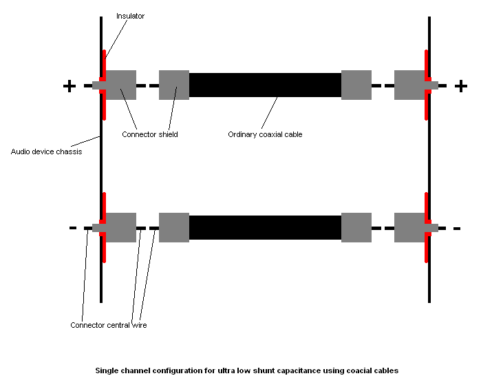
Instead of connecting a single coaxial cable for carrying both positive and negative signals (channel and ground) let's use two coaxial cables per channel to achieve the same result. The middle wire of the first coaxial cable will carry the positive signal and the middle wire of the second coaxial cable will carry the negative signal (audio GND). The shields of both coaxial cables must be insulated from the chassis and no other connection must be made on them, they are left unconnected. Using this arrangement, we transform the coaxial into a parallel set of cables, each of them having its own shield. The un-connected shield will still provide some short of shielding from the high frequency radio waves, but of course not so strong shielding as if it was connected to the ground. The shunt capacitance is minimized, as if we had two parallel wires and air dielectric between them, but now we have introduced a modest shielding for each of them. Using this technique, you must have four cables total instead of two for both channels and you also have not so strong shielding, like the ground connected shield of the coaxial cable. This is the price to pay for the ultra low shunt capacitance.
The great thing when you come into construction of the cabling, is that you do not need to throw away your existing cables and connectors. You just use an extra pair of coaxial cables. You have to add more connectors to your audio device though and insulate their shield from the chassis of the device, if you want to use your existing cables. The picture below summarizes the construction of the ultra low shunt capacitance configuration for a single audio channel.
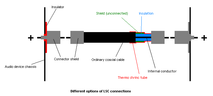
Sometimes I found it quite difficult to find insulators for the BNC connectors that I use. Also sometimes I did not want to mount the connectors on plastic or wooden box surfaces because I need the amplifiers to be completely isolated from any potential outside RF, so I need the whole box to be metal. Thus in some cases I decide to mount the connectors directly on the chassis, and alter my coaxial cables accordingly. I just use uninsulated connectors and leave the shield of the coaxial unconnected. This has the disadvantage of a little less mechanical stability, so to overcome this, a little bit of glue or hot silicone between the cable insulation and the internals of the connector helps. Below I present you this alternative configuration for the LSC, if you do not want to use chassis insulators, in comparison with the insulator use technique.
Disclaimer notice: Information and files in
this page provided as is. You are free to copy any
images and data in this page provided that you do not alter their content and
you clearly define their source.
Copyright
© 2009-2010 - All Rights reserved