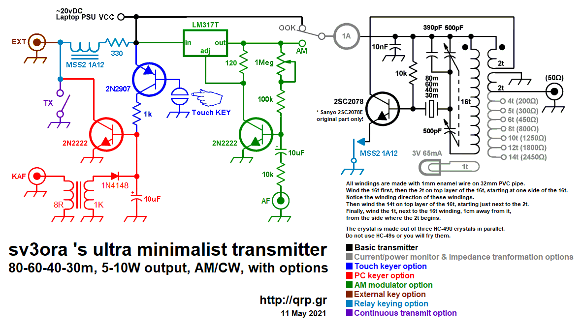
sv3ora's ultra minimalist
transmitter
80-60-40-30m, 5-10W output, AM/CW, with options

Introduction
The "sv3ora's ultra minimalist transmitter" is an evolution and combination of the EMTX and its keyer. It is an ultra minimalist
CW and AM transmitter that covers 80-60-40-30m and any in-between
frequencies by just plugging in the appropriate crystal. The
transmitter has many options, denoted with different colors in the
schematic diagram and you can include or exclude options, so that you
can build your own version depended on your needs. The
transmitter is capable of providing up to 10W of output power on CW with the voltage shown,
depended on the band and the variable capacitor setting, into 50 ohms
load. On AM it is capable of providing around 4W of average output
power with good modulation, but the idle carrier level can be set anywhere from 0.5-8W.
Components selection
The transistor:
This transmitter has been designed so that it can operate with any NPN
BJT in place. Despite 2sc2078 is shown in
the schematic, just
try any NPN BJT
in place and adjust the variable capacitor
accordingly. Some of the most
powerful transistors I have used, come out of old CB radios, such as
the 2sc2078, 2sc2166, 2sc1971, 2sc3133, 2sc1969 and 2sc2312. There are
many others. As an example, the 2sc2078 with a 20v laptop PSU, gave
more than 10W of output power into a 50 ohms load on 40m. I recommend
to use the original Sanyo transistor on this. I find that Sanyo 2sc2078
transistors give the best chirp performance.
The crystal:
This is the most uncommon part of the transmitter. You have to find the
crystal for the frequency that you want to operate on. Crystals within
the 40m or 30m CW segments are not that common. Further more if you
operate the
transmitter at high powers and currents, you will notice severe crystal
heating and lots of chirp. The current
handling capability of your crystal die inside the crystal case, will
determine the chirp and the amount of crystal heating. You can still work
stations with a chirpy transmitter provided that the chirp is not that
high, so that it can pass
through the CW filters of the receivers. However, if a small chirp
annoys
you or if this chirp is too much, then you have to use HC-49U crystals
and connect 3 of them in parallel. Also, these vintage
bigger size FT-243 crystals can handle
more current through them, but these are evem nore uncommon
today.
The
approach I have used in my prototype, was to connect 3
HC-49U crystals of the same frequency in parallel, so that the current
is
shared ammong them. This reduced the chirp at almost unoticeable
levels and it was even better than that of a single FT-243. You do not
have to match the crystals, although some combinations might have a
better chirp performance than others. A bit of warning, do not use
HC-49s crystals on this transmitter because you will fry them.
The current meter:
A
1Amp (or even larger) current meter can be used to monitor
the current drawn by the
transmitter during key down. The recommended current operating point is
anywhere between 450mA to 1A, depended on the output power (and
harmonics) level you want to achieve. The current point is set by the
variable capacitor. I would avoid setting the current to more than
1Amp, although it can be done. The use of the current meter is
optional, but along with the
incandescent bulb, will give you a nice indication of the correct
tuning of the transmitter, so that you do not need to have an external
RF power meter connected to the transmitter output. If you do have,
then you can remove the current meter. If you don't have a
1Amp analogue meter available, but a smaller one, you can parallel a
low value power resistor accross the meter. In one case, I only had a
100uA meter and I paralleled a 0.15 ohms 5W resistor accross it to
scale down 1Amp to 100uA, The resistor value depends on the internal
meter resistance so you have to calculate this for your specific meter.
When the 2sc2078 is used at 20V, 500mA in the current meter indicates
around 5W of output power, 600mA indicates around 6W,
700mA 7W, 800mA 8W, 900mA 9W and 1A around 10W. So the current meter
can be used as sort of power meter without the need to do any scaling
on it.
The incandescent bulb:
A current meter
alone, without the use of the incandescent bulb, will not give you the
right indication of the operation of the transmitter. In some cases,
the transmitter
might be drawing current without actually generating much, or even any
RF.
The incandescent bulb will light on, when the
transmitter
oscillates. It monitors the actual RF signal, so it's brightness
changes according to the amount of RF power the transmitter produces. Along with the
current meter reading, this
is just what you need to know in order to set the variable capacitor
properly. Note that the bulb will not lit at very low
signal levels. The one used in the prototype starts to glow up from a
bit less
than 1W. Miniature incandescent bulbs may not be that easy to find
nowadays. However, there is a good source of these, that almost anyone
has in their houses. This source is the old Christmas lights. You do
save old Christmas lights, don't you? The incandescent
bulb indicator as well as it's single turn winding on the transformer,
are optional components. If you have an RF power meter connected to the
transmitter, you can remove these.
The variable capacitor:
The variable capacitor is a dual section (500pF each section) air
variable. Note that in this application, you have to isolate the
variable capacitor from the chassis (if a metal one is used) and from
your hand. So use a non-conductive knob and make sure that the mounting
screws of the knob do not come in contact with your finger.
The relay:
The relay directly shorts the transistor emitter to the ground, therefore
it is a part of the active circuit. For this reason, I suggest the relay
leads to be kept as short as possible. The relay must be able to handle
the voltage (20v) and switching current (up to 1A) on it's contacts, which is
usually not a big deal. I used a reed relay so as not to hear any noise during keying of the transmitter.
The AM modulator
In the old days, the most common way to apply AM modulation was to
modulate the high voltage to the plate of the tubes, using a
transformer and a powerful audio amplifier. In low voltage solid state
circuits, you can still do it using transformers, but you can also use
series transistors instead of the transformer. All these things require
many components and/or powerful AF amplifiers if one is to modulate
higher power transmitters. This does not match the keep-it-simple
design I am trying to achieve here.
So I thought of a simple trick with the use of the extremely common
LM317 regulator, used as a modulated power supply. This modulator uses
just a few common cheap components and it is able to achieve remarkably
good modulation levels for it's parts-count, just from line audio
input. It juices every bit of the internal circuicity of the LM317,
just look at where the base current of the 2N2222 comes from.
The AM modulator is a kind of novelty. Whereas there is nothing special
in a modulated power supply, this circuit has some interesting
properties. It is amazingly sensitive and it is able to provide lots of
modulated current to any low power transmitter that it can feed. It can
be easily driven by the line output of any laptop (around 20% volume)
and provide a very good depth modulation to the transmitter. Charles
Wenzel was kind enough to do a simulation on the circuit I developed,
which is shown below.
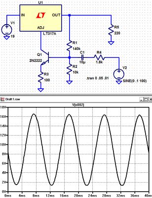
His simulated circuit is a slight variation (for measurement purposes).
The resistor to ground on the base stabilizes the bias and the ratio of
R1 and R2 set the output voltage (0.6 volts across R2 gives about 8
volts across R1). He put in an emitter resistor just for good measure.
Same for the series resistor from the source. Charles words, "I don't
know how believable these results are but it looks pretty darned good!".
The circuit is being used as a current booster, the current being the
supply to the transmitter and dependent on the voltage it produces. The
LM317 always tries to keep 1.25V between it's output pin and "adj" pin
but where we benefit here is the current at the "adj" pin is very low,
so it is easier to apply audio to it. Effectively, the error amplifier
inside the voltage regulator is used as an additional amplifier stage.
The output pin voltage varies according to the voltage on the "adj" pin
so if we use it to bias the transistor we get negative feedback which
improves the quality of the modulation. More output voltage = more bias
current = lower output voltage. The result, is a very cheap, low
components-count, very sensitive AM modulator that can supply lots of
power to easily drive the transmitter and produce a clean and deep AM
modulation!
The AM modulator bias is set with the 1M potentiometer. Depended on the
bias level, the idle carrier on the transmitter can be set from about 0.5W all
the way up to 8W. Needless to say that this modulator can modulate any
similar power transmitter, not just this transmitter.
The keyer
If it is to modulate the transmitter from the PC, so as to use the different
digital modes, there must be a way to key it also from the PC. This is
why I decided to embed into the same circuit, a PC keyer which is
triggered by the line audio of the PC, but also triggered manually
(internal or external key). Keying by audio tones was decided, because
modern PCs do not have LPT ports to trigger directly by DC. This keyer
uses a reed relay to reliably, fastly and scilently key the transmitter, which
is activated by a transistor. The base current for the transistor is
derived from the audio signal after rectification. The incoming audio
from the PC line passes through the mini audio transformer to increase
its voltage, it is rectified and then charges the shunt capacitor to
drive the base of the transistor. The keyer "speed" (decay) is
determined by the shunt capacitor size. The circuit starts to trigger
from about 50-60% of my sound card output signal level.
The relay used to key the transmitter, must be able to tolerate at least 1A of
switching and carrying current. Note that the relay contacts switching
current is not the same as the contacts carrying current. Reed relays
are the best especially if you want long relay life, noiseless
operation and very fast switching speeds, like the ones used in
Hellshreiber. If you can't find such a relay, you can use a reed switch
capable of 1A of switching and carrying current and then place a
suitable electromagnet close to it, so you can build the relay
yourself. If you do so, find the best point where the reed switch
responds to the electromagnet. The keyer relay must be as close as possible to the emitter of the
transistor used in the transmitter.
The keyer does also have an internal touch key. I find this
idea very nice, to avoid extra cables and to avoid mechanical complexity.
Initially, I used one channel of the PC sound card for triggering the
keyer and also as an AF signal for the AM modulator, but this caused
several problems of unreliable keying or distortion. So I decided to
use a second separate AF input (KAF) to key the keyer. This second
input, uses the other channel of the stereo sound card. With the
addition of this input, there is no interaction between the keyer and
the modulator. The AF levels that the keyer and the modulator require,
can be set independently. Instead of adding more hardware for the
purpose, I have chosen to set these levels by adjusting the volume and
the balance of the sound card, which works great. Also, programs like
Fldigi, have options for using one of the two channels of the stereo
sound card as a keying interface (PTT channel), which makes the keying
efen more reliable. When the program is in transmit mode, a continuous
tone is heard on the PTT channel. This steady tone, is used by the
keyer as a reliable keying signal, independent of the audio signal of
the digital mode that modulates the modulator. This solution works very
reliably for any mode. But if the program you are using does not have
an option for a PTT channel, that is ok, as the keyer works reliably
even without this feature. For voice communication or broadcasting
music (into a dummy load) you just use the internal TX switch as a PTT
to handle these modes.
Results
Prior to building the keyer and the modulator in the same device, I had
tested the circuits independently quite a few times, to ensure the
results can be reproduced. The modulation quality and depth out of the
AM modulator have to be listenned to be believed. I have not made any
linearity measurements, I just trust my ears on this one. It works
great on music as well as on voice. Apart from that, this is the most
sensitive AM modulator I have ever built, requiring only a small
fraction of the line level output of the PC sound card.
When modulated by this modulator, the transmitter shows no audible signs of FM
modulation. I switched my receiver to SSB and I could perfectly zero
beat the AM modulated music signal which stayed on frequency and it's
tone did not change during loud audio signal music. Switching back and
forth from SSB to AM modulation on the receiver, I did not notice any
difference in the audio quality, apart of course from the narrower
bandwidth on SSB modulation, due to the narrower IF filter inside the
receiver on SSB.
Transformer construction
The
construction of the transformer is shown below step by step. Note that
if you decide that you don't need to drive higher impedance loads but
just 50 ohm ones (eg. antenna tuners or 50 ohm matched antennas), you
just need to wind 2t in the secondary and not 14t. You also don't need
any taps of course.
Step
1:
Take a piece of 32mm external diameter PVC pipe from a plumber's shop.
Alternatively, a suitable diameter pills box can be used, or any other
suitable diameter plastic tube.
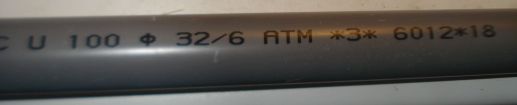
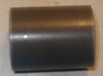
Step 2:
Cut a 4cm piece out of this tube. 4cm is the minimum length required.
Below a 4cm PVC tube
has been cut in size.
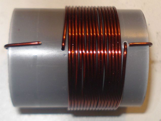
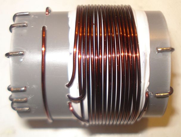
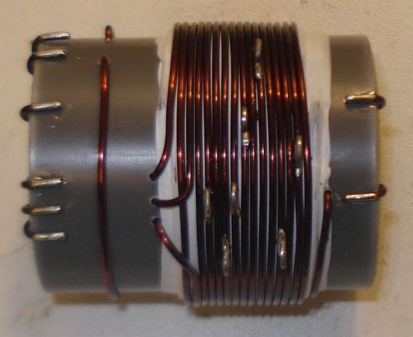
Step 3:
Wind
16 turns of 1mm diameter enameled wire onto the PVC pipe and secure the
winding in place as shown in the picture below. Notice the winding
direction of the wire. This is the primary of the transformer, the one
that is connected to the two capacitors. Notice that this winding is
wound a bit offset to the right of the pipe.
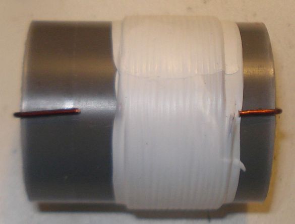
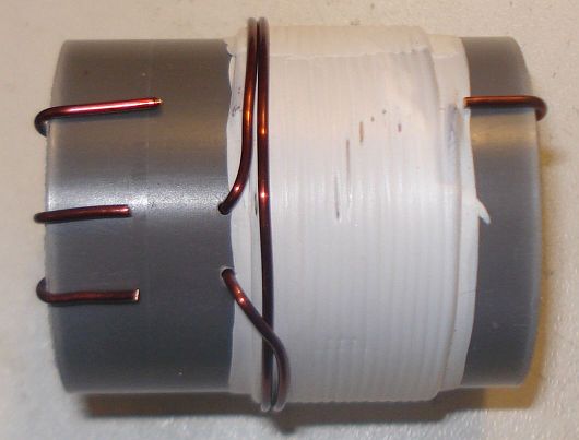
Step 4:
Wrap
the winding with 3 turns of PTFE tape. It can be bought at any
plumber's shop, just like the PVC pipe. The PTFE tape will help in
keeping the second layer turns in place and it will provide extra
insulation.
Step 5:
Wind
2 turns of 1mm diameter enameled wire on top of the primary winding and secure the
winding in place as shown in the picture below. Notice the winding
direction of the wire, as well as it's position relative to the primary
winding. This is the feedback
of
the transformer, the one that is connected to the collector of the
transistor.
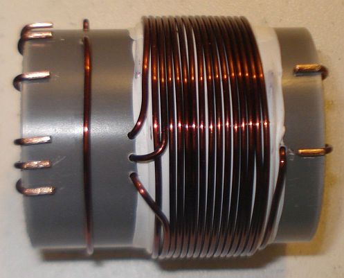
Step 6:
Wind
14 turns of 1mm diameter enameled wire on top of the primary winding,
starting from just next to the 2 turns one and secure this
winding in place as shown in the picture below. Notice the winding
direction of the wire, as well as it's position relative to the primary
and the 2 turns windings. This is the secondary
(output) of
the transformer, the one that is connected to the antenna. At this
point do not worry about the taps yet.
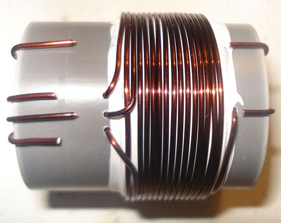
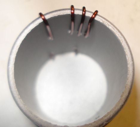
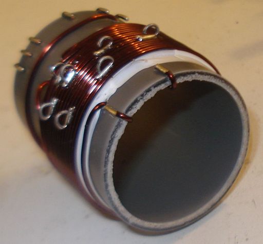
Notice
in the picture below, the way the windings are secured in place onto
the pipe. The wire ends are passed through the pipe using small holes
and then bent towards the ends of the pipe and once more to the surface
of the pipe, where the connections will be made.
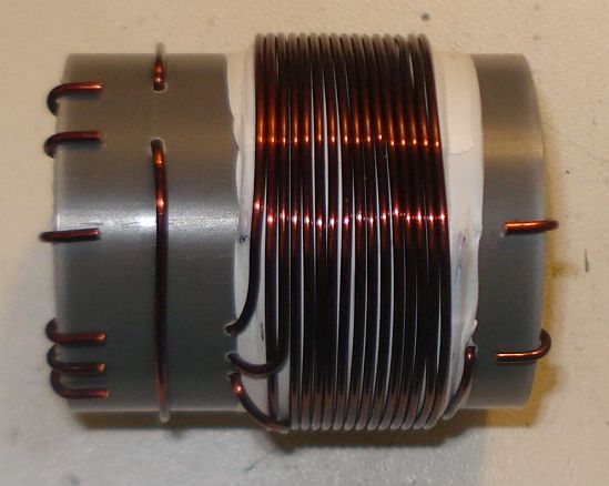
Step 7:
Wind
1 turn of 1mm diameter enameled wire onto the pipe and secure the
winding in place as shown in the picture below. Notice the winding
position relative to the other windings. This
1 turn winding is placed about 1cm away from the other windings. This
is the RF pick up winding, the one that is connected to the
incandescent bulb.
Step 8:
Use
a sharp cutter (knife) and carefully scrap the enamel of all the
windings ends. Do not worry if you cannot scrap the enamel at the
bottom side of the wire ends (that touches to the pipe). We just want
enough copper exposed to make the connection.
Step 9:
Tin
the scrapped wire ends, taking care not to overheat them much.
Step 10:
Now
it's time to make the taps on the secondary winding. Use
a sharp
cutter (knife) and very carefully scrap the enamel of the wire at the
tap points (number of turns).
Take much care not to scrap the enamel of the previous and the next
turn from each tap point. Do not worry if you just scrap the enamel at
the top of the wire (external area). We just want enough copper
exposed to make the connection.
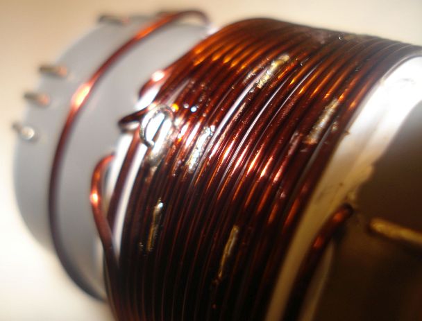
Make
each tap, a bit offset from the near by taps, like shown in the
pictures. This will avoid any short circuits (especially at the 4, 5
and 6 taps) and it will allow for easier connections, especially if
alligator clips are used to connect to the taps.
Step 11:
Tin all the tap points, taking care not to overheat them.
Step 12:
This
step is optional and it depends on how you decide to do the connections
to the taps. You may solder wires directly to the tap points, but in my
case I wanted to use alligator clips, so I did the next: I took a piece
of a component lead and soldered it's one end to each tap point. Then I
bent the component lead to U-shape and cut it accordingly. This created
nice and rigid tap points for the alligator clip.
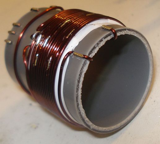
Step 13:
This
step is optional and it depends on how you decide to mount the
transformer to your enclosure. In my case, I wanted to create three
small legs for the mounting. I cut three pieces of aluminum straps and
made holes at both their ends. I made three small holes onto the
transformer pipe end and mounted the aluminum
straps using screws. After mounting them, I shaped the straps to
L-shape. Then I used
three more screws to mount the transformer to the enclosure.
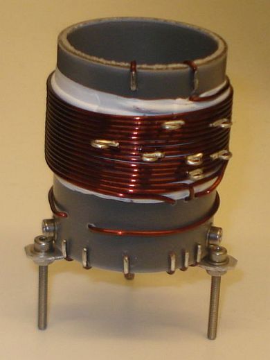
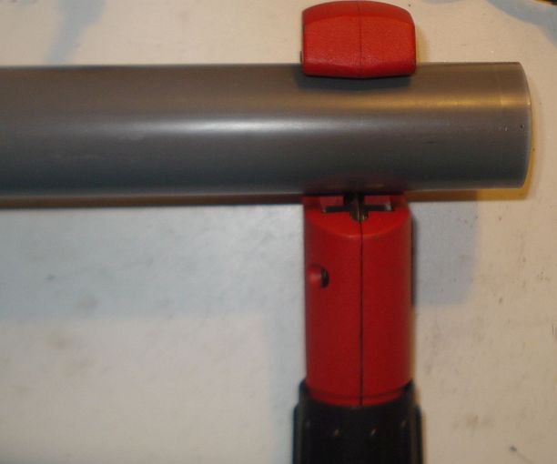
The
completed transformer is shown in the pictures above and below. The 6
connection points at the bottom of the pipe, are the low voltage
points, whereas the 2 points at the top of the pipe, are the high
voltage points.
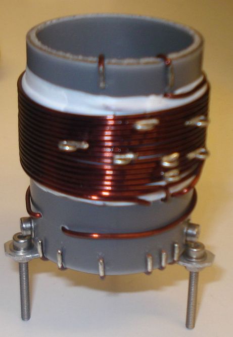
If you have built the
transformer as described, the bottom connections are as follows (from
left to right):
Wire end 1, connected
to the incandescent bulb
Wire
end
2, connected to the incandescent bulb
Wire
end
3, connected to the current meter
Wire
end
4, connected to the current meter
Wire
end
5, connected to the GND (ground)
Wire
end
6, connected to the transistor collector
The top connections
are as follows (from left to right):
Wire end 1, connected to the
25pF variable capacitor and the Cy fixed.
Wire
end
2, is the 14th secondary tap and it is left unconnected, or tapped to
the appropriate impedance antenna.
Videos of the transmitter in operation
I have made two small
videos of the EMTX transmitter in operation. Since this transmitter is an enhanced version of the EMTX, it works the same.
The first 13.5MB video
(right click to download), shows the operation when the transmitter is
set for a bit less than 10W of output power.
The second 3.5MB
video (right click to
download),
shows
the operation when the transmitter is set for about 5W of output power.
Transmitter chirp analysis
Every
self-exited power oscillator (and even many multi-stage designs)
exibits some amount of chirp. Chirp is mainly considered as the sudden
change in frequency when the power oscillator is keyed down. Apart from
chirp, there is also the longer term frequency stability that may be
considered. The chirp in the transmitter is surprizingly low, if it is built
properly. Hans Summers, G0UPL has performed a chirp analysis on my transmitter and the transmitter built by VK3YE and presented on youtube.
Hans, performed the analysis from the video/audio recordings of both
transmitters. I sent him two videos, one with the transmitter set for an
output power of 10W and one where it is set for 5W. The chirp at worst
case (10W) was about 30Hz and at 5W in the order of 10Hz or so. Being
so small, the chirp is almost undetectable by the ear and it surely
poses no problems when passing the tone through narrow CW filters. This
is an amazing accomplisment from a transmitter so simple and so
powerful.
Transmitter harmonics measurement
Every unfiltered
transmitter will excibit harmonics at it's output. This means that the
output waveform has some distortion in comparison to a pure sinewave.
Many of the transmitters I have seen, present a very distorted output
waveform and absolutely need a LPF if they are to be connected to an
antenna. I can't say that this is true for the transmitter, because
surprizingly, it has low distordion, despite the high output power it
can achieve. Although a LPF is always a good idea, it is not that much
needed on the transmitter. However you have to use one to comply with the
regulations.
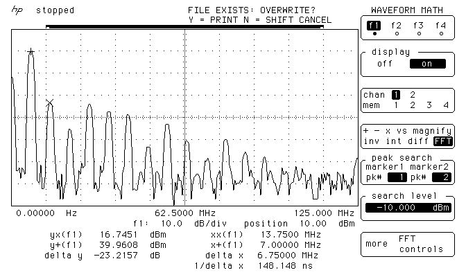
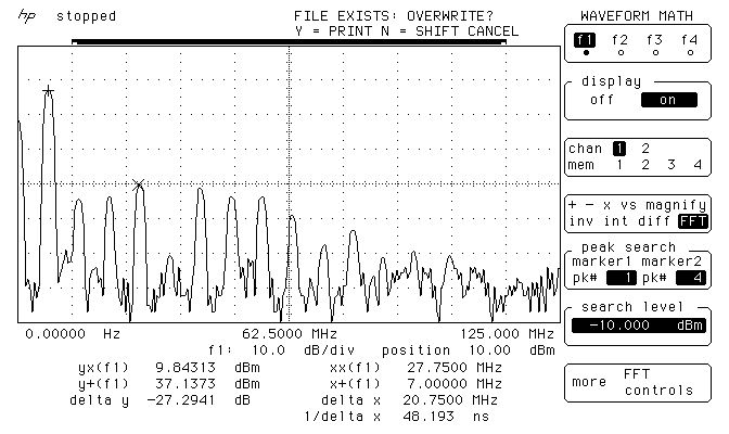
The
image above, shows the measurements on the output of the transmitter, when it
is set closely to 10W at 50 ohms. The main carrier is exactly at 9.9W
and all the harmonics are less than 50mW! Also, the harmonics, do not
extend into the VHF region.
The image below, shows the
measurements on the output of the transmitter, when it is set closely to 5W
at 50 ohms. The main carrier is exactly at 5.17W and all the harmonics
are less than 9.6mW! Again, the harmonics, do not extend into the VHF
region.
These
small harmonics levels aren't going to be heard very far at all,
compared to
the powerful carrier. This means only one thing. A LPF, although a good
practice, is
not mandatory in this transmitter. But you should better use one so
that you comply with the regulations.
Many
HAMs use just a watt meter to measure the output of their homebrew
transmitters. This is not the proper way of doing it, because the watt
meter is a non-selective meter. It will measure both the fundamental
carrier and the harmonics, without being able to distinguish them. So
in an unfiltered transmitter, or in a transmitter with a simple (often
non measured) LPF, this way will give a totally false reading of the
output power of the transmitter at the set frequency.
The proper way of accurately measuring the output power of a
transmitter and the harmonics levels, is a spectrum analyzer. The FFT
available in many modern oscilloscopes, having a dynamic range of
approximatelly 50-55dB, is adequate for this purpose as well. A 50 ohms
dummy load must be connected at the transmitter output and then the
high impedance probe of the scope, is connected to the output of the
transmitter as well. This was the way that the above measurements have
been performed.
WebSDR tests
Here are some
test transmissions, to determine how far one can get with such a
transmitter. I have to say that there is an antenna tuner between the
transmitter and my inefficient short dipole (not cut for 40m and not
even
matched to the coaxial). However I could still cover a distance of more
than 2500Km even on the 5W setting.
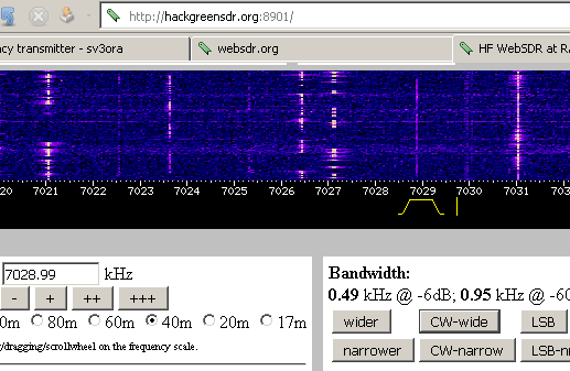
Above,
is a picture of the transmitter signal, as received on a WebSDR 2500Km
away and when the transmitter is set for an output power of 10W.

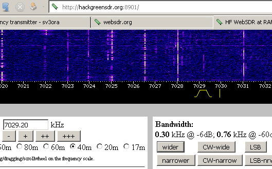
Below, is a picture
and an audio recording of the transmitter signal, as
received on the same WebSDR and when the transmitter is set for an output
power of 5W.
Back to main site