As the single board microcomputer systems in the early 80's got cheaper and easier to use, the home user started to realize their power and how important they were as general use machines. The same computer could be used for many different jobs provided that suitable programs were written. The abilities were only limited by the amount of processing power, memory and I/O devices all of which were primitive these days. Nevertheless, the experienced user, could usually overcome some of these problems by the use of sophisticated software.
Since then, technology has much advanced and the need for more power, flexibility and compatibility, eventually led to the PC as we know it today, a hugely flexible powerful but also very complex machine with almost unlimited capabilities. Most of the operations and the internals of the PC are entirely unknown, not only to the average user, but also to the programmer that has to write programs compatible with the PC architecture. Is this to be considered good or bad? What is known for sure, is that our programs have become way too much inefficient. Users do not care about the quality of the software they develop and the actual hardware, since power and memory seems virtually unlimited. This leads to speed decrement, regular system crashes, wasting of resources and power extensively.
Embedded systems have followed a more efficient way, by using only the needed hardware to perform each task and consuming considerably less power. As an example, Alix-1D PC engine offers all the I/O ports that an average computer can have and enough power to browse the web or perform other tasks. The whole computer board consumes a total of 5W and the CPU runs at 500MHz. This is an older example, but more recent embedded systems have become so powerful, that replace in many cases even the most powerful average PCs (raspberry PI etc).
These systems are very powerful, but the main disadvantage is that they cannot be built from scratch from the home user, as the complexity is prohibiting and the components used are really small and difficult to solder. Besides, there are not many cases one will need so much power for the home lab. Usually, a small microcontroller is more than enough for most of the projects you can build.
Microcontrollers are complete micro-computers in a chip and they are really promising devices. They have become much powerful today, so complete systems can be built using them. Nevertheless they have their disadvantages:
- Programs must be written for the specific microcontroller used each time.
- Usually too difficult to code.
- Perform one specific task per project.
- A suitable programmer is needed to burn code into the microcontroller.
- They depend on a PC to write programs for them.
The idea I was looking, was an easy to build, more generalized system that could eliminate the above disadvantages. I knew that the solution would lie somewhere between microcontrollers and advanced programming. After a long time searching, I found a very nice project (translated local copy), which I am trying to implement in my own way here.
This project describes a complete mini computer system that you can be build easily from scratch. This computer has been designed especially to meet the needs of a small homebrew lab. Everything is homebrew, there are not other prepackaged computers or modules used.
Introducing the ALMS System design
On the web, there can be found very nice projects about instruments for the lab. Frequency counters, components measurements, logic analyzers, even small oscilloscopes can be utilized using microcontrollers. Each one, uses it's own microcontroller and microcontroller dedicated suitable software that performs the specific task. Some of them, perform more complex tasks but they are not generalized, no way. You have to build the whole project with another microcontroller to be able to perform this specific task.
To avoid the extra hardware complexity, reduce cost and at the same time to enable more features to the measuring equipment (or easily updating them), I have thought of a flexible system that I called ALMS (Adaptable Lab Measurements System). In this system, I use the mini computer project described in this article, as the main computer for data processing, display and program entry. The rest of the measuring lab system, is based around this computer. The main diagram of the ALMS, is shown in the picture below.
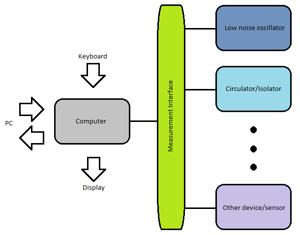
Overall ALMS system architecture
This is a very flexible system that can be adapted to many projects, using appropriate non-microcontroller-specific software and minimal hardware and cost.
The mini computer, shown in gray, can be programmed from the keyboard or a remote PC using a version of the BASIC programming language and it displays data on a screen through a suitable cable adapter. The computer undertakes all the tasks related to data entry, receiving, processing and results displaying.
The computer is connected to the measurement interface, which is an intermediate device, specifically built to interface the computer data terminals to the measurement or sensor devices, when the internal computer chip interfaces are not dedicated for the task. In general, it translates the input data in a form that the computer can understand and it translates the output data from the computer in a form that the measurement or sensor devices can understand. The type of hardware in this interface, is dependent on the specific measurements that need to be done and it is kept to minimal. Some examples of the hardware inside the measurement interface are sinewave to TTL converters, diode detectors etc. The rest of the functionality is performed by suitable software inside the computer. Additionally, the measuring devices or sensors can not only be connected directly to the measuring interface, but also between them, to create more complex systems.
By loading a different software and altering or re-routing some of the components of the measurement interface, you can adapt the system to a completely different project, without having to change the microcontroller. You are also not required to consume time to write microcontroller-specific-code (you are still allowed to do so if you want though). All you need to know is the rules of the BASIC language used, which are fairy straight forward and easy to understand. The key point to hardware minimizing is to make the measurement interface as generalized as possible, to cover in a general way the interfacing of all the measurements an average lab needs.
Once the system is up and running, it is completely independent from the PC. Programs can be created or edited in the embedded editor and run directly.
An example of the ALMS usage
To give you an idea of how easy is to implement a project that is based on the ALMS, I would like to give you an example. Suppose we need to create a frequency locked loop system, to keep the frequency of a VCO stable.
An ordinary approach would require the creation of a microcontroller project with microcontroller-specific-software to count the frequency in from the VCO, making some calculations and output the appropriate voltage pulses to correct the frequency of the VCO. Also some limited user feedback could be displayed on a seven segment display or a two-line or four-line LCD.
This is exactly the thing that has to be done in the ALMS approach. The major differences is that the code is done in an easy to program language and that the hardware required to make this project is kept to minimal. Supposing you have already built the ALMS, you only need to write appropriate BASIC code and possibly installing some minor components inside the measurement interface (if not already there). Also, user feedback is not limited to standard LCDs, but it can be extended to a full-sized display, creating complex diagrams and performing real measurements on the system.
Now suppose you want to convert the circuit to an antenna impedance measurement system using an additional circulator. In an ordinary approach this would require a massive effort in converting or completely re-writing the code for the specific microcontroller to meet the new requirements, burning the code into the microcontroller using a suitable programmer or interface which you must build or buy, and changing or adding some components on the PCB. If you continuously add or alter components to update features, the whole setup will eventually become very messy.
With the ALMS approach, such an alteration would only require fitting in the circulator and adding another single diode envelope detector inside the measurement interface (if not already there), to convert the sinewave signal out of the circulator to a voltage level and then to alter your BASIC software easily and run it, without re-programming the microcontroller, in order to monitor the voltage out of the measurement interface.
Additionally, you can display data diagrams in your screen that would be impossible with a common LCD before. You may for example monitor the voltage pulses to the VCO, the frequency of the signal as well as the detected voltage out of the circulator. Then continuously change this frequency and record data, to create complex diagrams of these three parameters. All these, completely independent of a PC or a programmer and easily coded.
Project files
Coming soon...
The circuit
Coming soon...
Overall construction
Coming soon...
Can it be made better?
Coming soon...
Thanksgiving
Coming soon...
References
Coming soon...