|
The goal of this project is to design and implement a small signal
preamplifier that sounds great, at a relatively low cost.
History
The idea behind the circuit took birth a cold Autumn noon in 2007.
People were staying inside and the beach was empty. The only thing that
existed was the gray waves the cold air and loneliness. Along with the
first rainy days I came to realize that the summer had ended...
This preamplifier is dedicated to my girl who understands and respects my
obsession in this state of art called vacuum tube. Thank you so much
Diamond...
Performance
I designed this preamplifier from scratch based on a weird tube. Not so
many designs are found on the web using this tube and I always enjoy using
RF tubes in audio. PC88 is a small low microphonics UHF triode used as
oscillator or amplifier in radio circuits. As in all my projects I tried to use the highest
quality parts I had available. The good point is that the preamplifier
sounds good even with cheap parts. If you want to keep the cost low, I
would advise you only replacing the 1uF 250V capacitor shown on Figure 1,
with a MKP or better. This gives a better transparency on the higher
frequencies.
Although the final amplifier used to test this circuit is a class-AB
amplifier, the preamplifier introduced a vast amount of bass that could be
noticed even from the very early tests. Also, the bass is warm as expected
from a class-A circuit operation and extends up to the human listening
limits.. The mid-range is very clear and the women voices sound quite
bright. The high frequencies are very transparent and extend up to the
human listening limits too.
The Circuit
The main line stage of the preamplifier can be seen below.
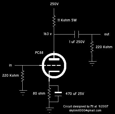
Figure 1. The preamplifier signal section
The test power supply used was
very simple and low cost but I was surprised to say that it performed very well
for it's simplicity. The noise was almost undetectable and there was no hum at
all. On Figure 2 the test PSU can be seen. I had to isolate the 220v but the
custom made transformers at these voltages are more expensive and not so easy to
find. So I decided to use two fluorescent lamps transformers connected opposite
to each other. That is, connecting the two secondaries together. These
transformers have a very low cost and are commonly available. The drawback is
that they have low efficiency and they get very very hot. So do not mount them
on anything else than metal and try to keep them away from heat sensitive
components. Make sure that they get fresh air to be cooled down. The way I have
connected the transformers degrades even more the performance of the PSU but I
do not need a high performance PSU here actually. The result is exactly what I
need and I do not bother spending more money for this test PSU version.
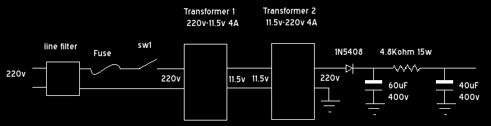
Figure
2. The preamplifier PSU section (test version)
Although the test PSU version
performed well, the next PSU was build as a final one. Among other features, it
protects the tubes from cold high voltage and the filaments from surge. It also
provides a mechanism to discharge the high voltage capacitors when not in use,
so no more HV burns when servicing.
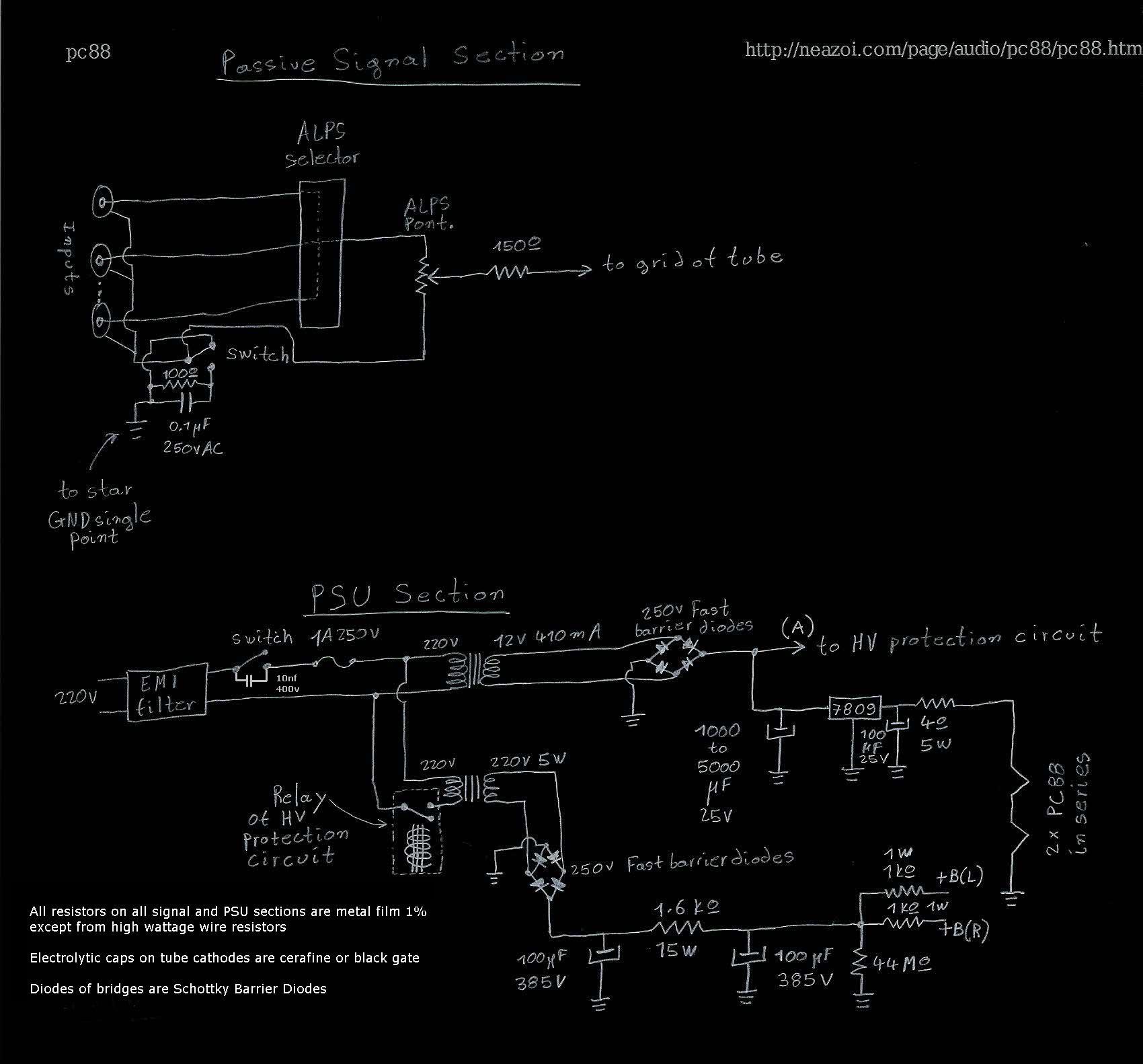
Figure 3. The final PSU and line
input circuits (click on the image for a clearer view)
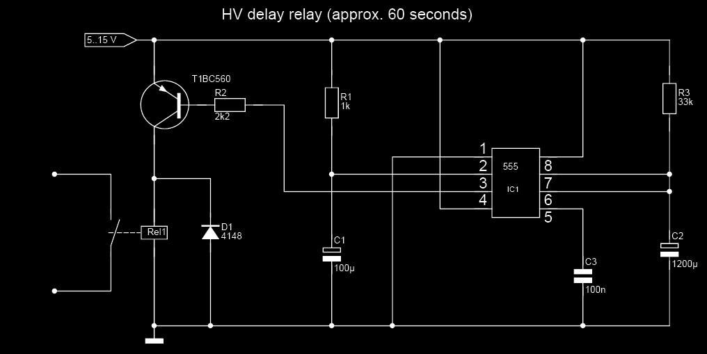
Figure 4. The HV protection
circuit that must be connected to the relay

Figure 5. The experimental setup

Figure 6. The final PSU

Figure 7. The final line section

Figure 8. Before the box closing

Figure 9. The back side of the
box

Figure 10. The front corner
finishing. Wood, metal and polished flexi glass

Figure 11. The finished
preamplifier. View 1

Figure 12. The finished
preamplifier. View 2
Useful data
1. PC88 Datasheet
Some technical
issues from the diyaudio forum about the circuit
Question:
hi I designed a simple SE triode preamplifier that can be seen in the picture.
the preamp plays nicely and there is a vast amount of bass compared on my
previous preamp but I need a little bit of help on how can I bias it into
class-A operation. I know what I have to do to bias it but I do not know the
values of the components.
Should the mA at the anode be the maximum allowed by the tube datasheet?
This tube draws about 12.5mA at max and I only can make it draw 8.2mA, so this
is not class-A right?
Answer:
No, it is operating in class A for the amplitude levels you require otherwise
distortion would be severe. (Other classes of operation imply conduction over
less than 360 degrees.)
The component values you have chosen look reasonable for the tube type and
voltages you have chosen.
To increase plate current reduce the cathode resistor value, note that as
current increases the plate voltage will drop which will have the effect of
reducing the change in plate current that you would expect from a reduction in
cathode resistor value. Values between 47 and 100 ohms are reasonable, try a
couple of values in this range and determine which you like best. For lowest
output impedance a high quality bypass cap is recommended (given the several
hundred uF required it should be made up of several good caps in parallel.)
Alternately you could use something like 3 red leds in series in place of the
cathode resistor.
Question:
I used a 470uf bypass cap in order to extend a bit the range in the bass
section. The leds idea is great indeed.
Also I have adapted a potentiometer as cathode resistor and I change values
easily. Although I have never reached more then 8.2mA at the anode even if I set
the cathode resistor in small or large values... Maybe this means that the tube
is highly used? I do not know...
The sound is very acceptable though...
I was wondering of how could I push the tube to its limits to achieve a class-A
device but as you say it has to operate in class-A even if the plate current is
much lower...?
Answer:
This is a class A circuit. The grid resistors should probably be made smaller -
on the input and next stage as shown in your pic. 1M is maximum permissible
according to tube sheet. While they allow smaller bypass caps, I think a circuit
sounds better with lower value grid resistors. If you drive the tube hard - a
high value here can actually change the bias voltage causing you to lose
linearity. Try 220k, 330k and check your plate current and sound again.
If you aren't using a negative feedback loop, im not sure 100 ohms in the
cathode is enough negative feedback to keep distortion down. You say this sounds
OK?
Question:
I thought so about the grid resistors, It seemed too big to me too...
The strange thing to my point is that yes, the preamplifier sound good to almost
any value of cathode resistor with only small changes mainly in the bass
section.
What value would you propose for the cathode? smaller or greater? the datasheet
says recommended 100ohms that is why I choose so.
The high range transparency is very good when I change the MKT output cap with a
wima MKP and I guess it will be nicer with more expensive caps.
I think the greater the value of this cap the more extend in low frequencies?
For the input cap I choose to use the output cap of the previous stage (the one
inside a cd player, etc) and I preferred not to add another passive component
there...
Finally I believe a second identical stage will boost up the total gain, but
what the value of the capacitor between two stages can be? The same as the
output cap or smaller?
Answer:
Why do you need more gain? If you really do, choose a tube with a higher mu like
the 5842, Russian 6S4P-EV (both 40 - 50) or D3A (70) triode connected.
Minimizing the number of stages is always good for transparency. I'm very
minimalist in audio path design, and rather the reverse in psu design. First and
foremost this is a general explanation to your questions.
I would drop the grid resistors for linearity and lower noise. As for the
cathode R, there isn't a hard and fast rule - it depends on the circuit and the
voltage of your power supply. When you choose plate and cathode Rs, you are
defining the operating voltage of the plate, the bias voltage on the tube and
the current going through it. A safe and typical design is to run the tube at
about 60% of it's plate dissipation. In this case just under 1watt (I believe
this is a 1.8 watt tube). So you choose your plate and cathode resistors so that
you have that .95 watt dissipation, and the voltage on the plate is say 60% of
B+ so you have lots of headroom to swing AC voltage (your music signal) without
distortion. Make sense? So you choose resistors that make this happen - it's not
a rule where you always use 100ohms. Make sense?
Question:
The tube has a dissipation of 2W max.
I made the cathode R to 80 Ohm. The voltage drop across it is 0.65v.
So the current running through it is (0.65/80)*1000=8.125mA
With the same calculating method the current on the plate for 11kohm R is
(95/11000)*1000=8.636mA
They are very close together as would expected.
Now the tube has 2W dissipation as I said. As you suggest, 60% is 1.2W.
The plate voltage is 163v. From P=V*I we have that (1.2/163)*1000=7.361mA
Which is a bit lower than 8.636mA but still close so I am running the tube a bit
hotter but in safe area.
Also my +B is 250v and the plate voltage is 163v. That is (60*250)/100=150v
This confirms that I have run the tube a bit harder.
I would like no know two things in this post please..
Q1: I am wondering if my calculations are right (the way I do them)?
Q2: Even if you run a tube at 60% plate dissipation it still can be class-A.
These two are independent right?
Answer:
OK Again this is IN GENERAL. In a simple circuit under *ideal* conditions, there
is no grid current so the current through your cathode R, the tube and the plate
R is all the same. Think of it as a straight pipe. If you are getting some
variances, it could simply just be fluctuations in V in the power supply, your
meter... whatever.
As to the 2W rating - check your tube - the sheets I looked at were 1.8. Either
way, 1.2 watts is within rating and won't hurt anything. Your calculations look
ok at quick glance.
Now, let's try to clarify this - dissipation. For a simple voltage amp - there
is no need to run the tube this hard. You aren't generating power into
anything... However, tubes are generally more linear (and sound better) running
at higher currents. Look at the data sheets. The curves are straighter as the
current goes up.
Therefore, people try to find a balance between running a tube hard and tube
life (how long it will last). Thus the 60% or so guideline.
Now class of operation has nothing to do with dissipation. It refers to how much
of the music signal the tube carries. IN the case of a single tube voltage
amplifier you have here - the entire music signal is going through it - what was
said earlier - the full 360 degrees. That is class A - the tube carries ALL of
the signal. Class B is when the tube only carries part of the signal - in the
case of an output circuit with tube tubes - imagine each tube amplifies half the
signal. Then you put the 2 halves back together to have the whole signal again
(in the transformer). That's class B - where the tube carries less than the full
360 audio signal. AB is a function in between where the amp works class A at low
power and class B at high power - but that's not an issue here with your
circuit. Running anything other than class A here would create major distortion
and you couldn't listen to it.
|