Experiments on
circuits on
paper
by SV3ORA
The resistor
The graphite inside the ordinary (non mechanical) pencils is a resistive element and this can be used in our benefit to make homemade resistors. The graphite can be removed from the pencil by etching it or simply by burning out the pencil wood into a stove. When the graphite rod is accessible, a resistor can be formed by touching two points of the graphite with metal terminals. The problem with the graphite rod is that it is fragile. Also cost may be an issue, since you have to sacrifice many pencils to make many resistors. The process of taking out the graphite of the pencil is also more time consuming, it leaves dust and requires energy (the source of heat) to do so.
I thought that there is an easier alternative that offers some benefits over the graphite rod method. Simply, just draw resistors onto ordinary printer paper sheet! It is so easy.

The picture above, shows different resistors I have drawn onto a sheet of paper using different graphite hardness pencils. For size comparison, the first two vertical lines from the left hand side, are 1cm in length. The values of the resistors and the harnesses, are marked. In some resistors, measurements have been done on their length as well on their width. From this experiment, I have concluded in the next points:
The harder the graphite material is, the higher the value of resistance, for the same length. Harder graphite, contains more impurities like clay, which increases the resistance. For example the 6H graphite is so hard that the impurities are high and additionally not enough graphite can be deposited onto the paper, which causes a huge resistance that cannot be measured on the multimeter. On the other hand, 8B graphite is very soft, having low concentration of impurities and it can be deposited easily onto the paper. This decreases resistance per length unit.
When you draw the resistance, make sure you firmly press the pencil onto the paper, to deposit enough graphite onto it, so that the resistor is conductive throughout the whole resistor line.
There is nothing to stop you from paralleling resistors to get lower resistance values. Like in ordinary commercial resistors, paralleling two equal resistors yields in a total resistance half of their value. In fact, when I tried the softest pencil I had (8B), I found a lower limit of about 800R on a resistor length of a few mm. To get lower values, I paralleled two equally drawn resistors. The first two drawings in the picture above, show the effect of parallel resistors drawn in two big arcs. The outside arcs diameters are the same but in the second image there are additional inside arcs.
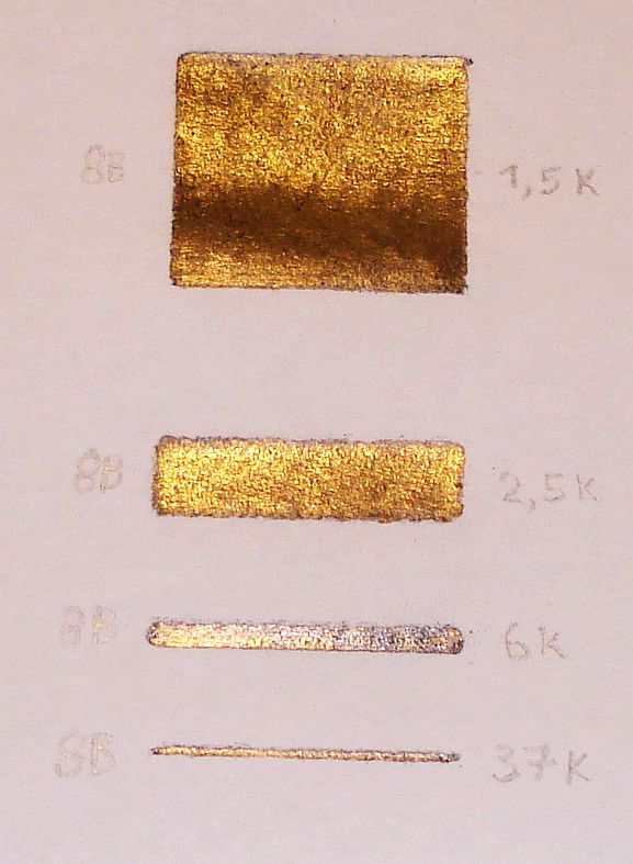
Paralleling an infinite amount of resistors, can be thought as a wide enough resistor line, with the multimeter ends connected not on the resistor length edges, but at the resistor width edges. This thought is verified on the picture below. Four identical length but different width resistors have been drawn, using the same graphite material and their values measured. Notice the huge difference in resistance as the resistors get wider and wider.

By drawing the resistors onto the paper, it turns out that if you need more precision on the resistance value, you might find more convenient to use a softer pencil and a longer resistance line, but resistor size may be a limit to because the bigger the resistor, the greater the inductive component that will be introduced, which is important in RF applications. If you need very high resistance values use harder pencil and adjust size accordingly. But there is a limit in the minimum resistor value using harder pencils. In either case, a single pencil can draw hundreds of resistors!
Having these points in mind, you can make homemade resistors at no time, that are flexible and ultra low cost!