by SV3ORA
Working around with digital electronics and small computer stuff, I found the need for a generalized prototype board for digital electronics work. I created a single sided board, in a way to minimize the amount or length of wires for point-to-point connections, especially for the PSU section. Additionally, it may save you a lot of time in wiring and debugging.
I designed the board on ExpressPCB design software, then printed it to PDF using a pdf printer. Here are the board files for download:
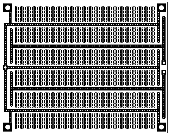
The board provides a GND and two other rails. For example, one of these could be +15v and the other one +5v. Another example could be GND, +5v and +12v. You can make any voltage combination, for example if you need only a GND and +5v throughout the whole circuit, you could bridge the two positive rails together.
The PSU rails are passing near every chip, so that no long wire bridges needed. The GND rail is physically connected to the four mounting screws of the board, so that it can connect to the chassis ground. The four holes for the mounting screws are of large diameter to allow using longer screws for multiple board stacking. If you want to build a greater scale circuit just stack one or more boards on top, using longer screws and spacers.
Drilling the whole board could be a nightmare. You just do not need to drill the whole board, drill only the points you need. Alternativelly you could drill only the IC sockets places and mount the components and wire bridges on the top side of the board without making any drills for them. Of course, the board then must be upside down and the IC sockets types to be the ones with long pins or just make them from ordinary hollowed pins sockets like this one. Or just make the wire bridges on the bottom of the board. You can make many combinations.
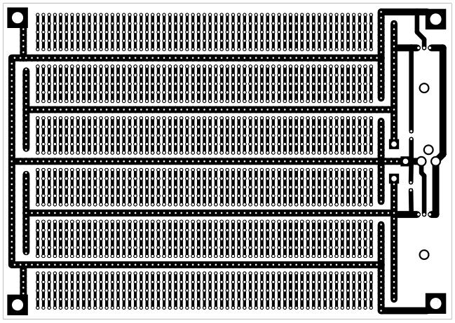
I have also produced a second version of this board with embedded PSU based on 78xx regulators. This version allows for even greater flexibility since it can be powered by any external unregulated jack wall. All TTL will work on a stabilized voltage of +5v, so why not include an embedded regulator on the board?
Here are the board files of the second version for download:
ExpressPCB
file
PDF file
Silkscreen layer
If you only need one voltage, mount only one regulator and wire the bridge in the middle. If you need two voltages, mount both regulators and cut the bridge in the middle. Obviously, if you mount only one regulator, only one electrolytic capacitor is needed.
The regulators are mounted horizontally on the board and there is enough space for two small heatsinks on them.