All waves RF generator
built and modified by sv3ora

An RF
signal generator is a special piece of test equipment, which allows you
to test a wide variety of RF circuits and perform many other
interesting RF experiments. For quite a few years, I was trying to
perform the RF experiments that required an RF source, using
purpose-built narrow band LC or even crystal oscillators. After the
tests were completed, I dissasembled some of these since I needed the
components and I had to rebuild them in the future to test new
circuits. When the oscillators were not dissasembled, they ended up in
the circuits junk box. More or less, I ended up with a whole bunch of
narrow band RF oscillators, most of them not usable for my next
projects that required other frequencies of operation. If you are really into RF, soon or later you are going to need a wideband RF signal generator.
Nowadays,
with the improvements in DDS technology, a digitally-synthesized
frequency-stable wideband RF signal generator with good characteristics
can be made at very low cost. It almost makes no sense to try to build
an analogue type RF signal generator, commonly composed of many
resonators, so as to cover a wide frequency range. But for the
homebrewer, the situation may be quite different. There are various
reasons for that. The DDS requires a microcontroller in order to set
it's frequency. The microcontroller requires a programmer hardware and
software, in order to be programmed. A PC is also required for the
programming operations. Quite a few of the homebrewers do not know how
to write a program to control the DDS and learning MCU programming is
difficult for many. Thus, they rely on programs others have built and
they cannot alter their operation to their needs. The DDS also requires
a stable very high frequency clock oscillator for it's operation
although the situation becomes a bit better (lower frequency needed) if
there are internal frequency multipliers within the DDS chip. Apart
from these things, soldering a DDS chip is a nightmare for the
homebrewer with little or no experience in SMD and it requires SMD
equipment. The tiny pinout of the DDS chips can be proven to be
challenging to solder, even for more experienced people and prototyping
is almost out of question. Finally, a DDS chip is a "black box" module
and there is no real satisfaction to the RF experimenter, since he is
not building any RF circuit, but just using a chip to produce the RF
without any chance to change it's RF characteristics. Take the time to
read the list of requirements in this paragraph and you will
immediatelly see why a DDS-based generator is not always the best
solution, practically speaking. Even the cost of the DDS that might
initially be thought as low, can be proven to be much higher at the
end, with all those mentioned requirements.
An
analogue RF signal generator instead, can be built with a few discrete
components soldered together with a common soldering iron and no
previous experience in SMD components or MCU-related things. Depended
on the generator circuit and the way of building it, the total cost may
be lower than that of a DDS generator and the resonators can be
home-built. In a DDS, the output waveform result is always the same
(guaranteed by the DDS chip specifications), if properly built. However
in an analogue type RF generator, the quality of the output signal
depends on many factors, such as the circuit topology, the RF
shielding, the mechanical stability, the Q of the resonators etc. But
you have a full control over these things and it is really up to you to
decide the best way to match your requirements and that is the beauty of it.
There are
poorly designed analogue RF generator circuits or poorly built, as well
as good ones or properly built. I have seen and tested quite a few
signal generators that appear on the net and on magazines but I wasn't
really satisfied with the end result of any of these. It is ok to build
a poor analogue RF signal generator if you only intend to do simple
things with it, but if you are going to use it for more serious work,
choose a circuit and method of construction that meet your tighter
requirements. Since you are going to do the effort and spend your time
in building an RF signal generator anyway, I would advise you to start
with a better quality circuit and build it as properly as you can,
based on your available time, your patience and the end result you try
to achieve.
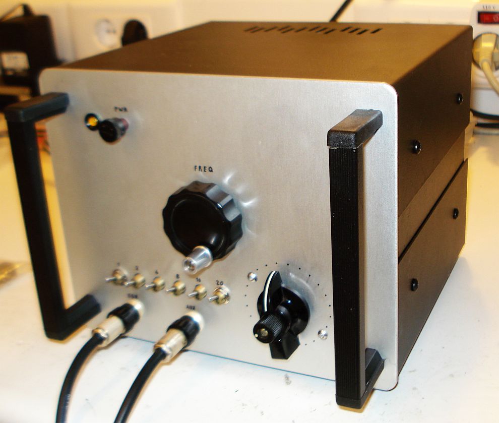
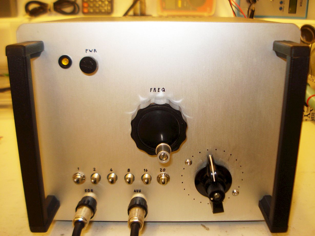
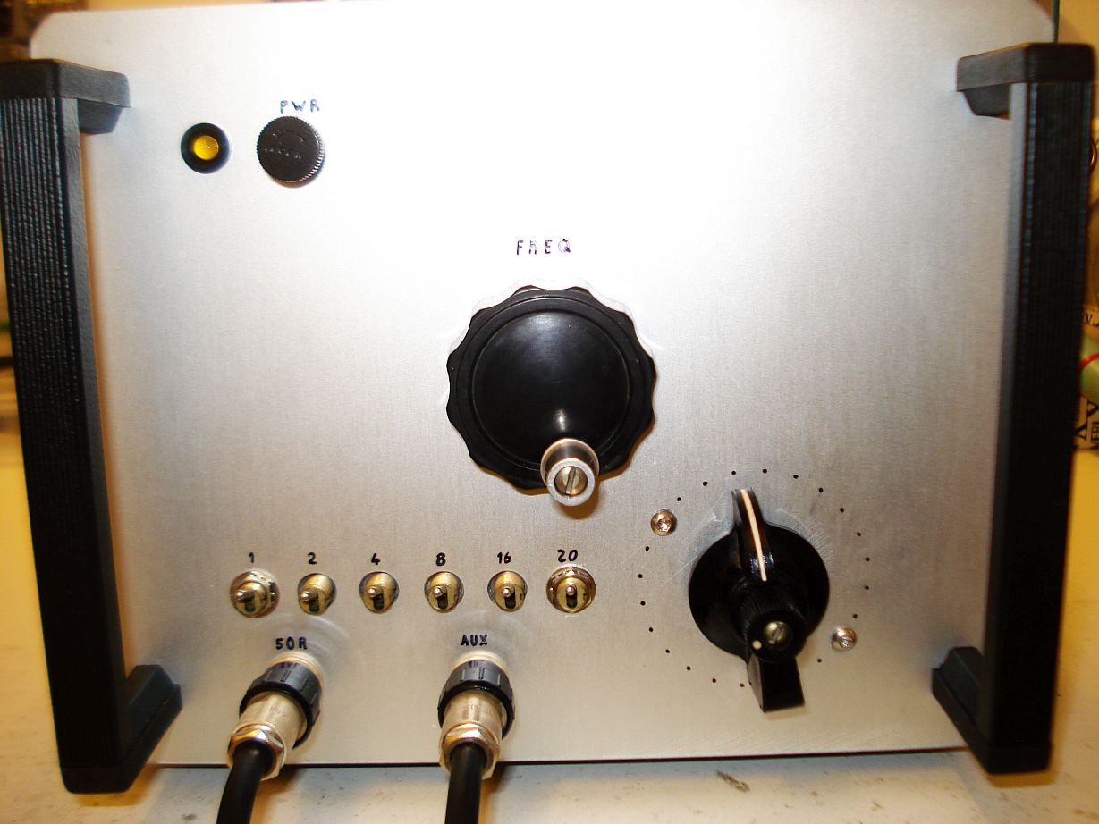
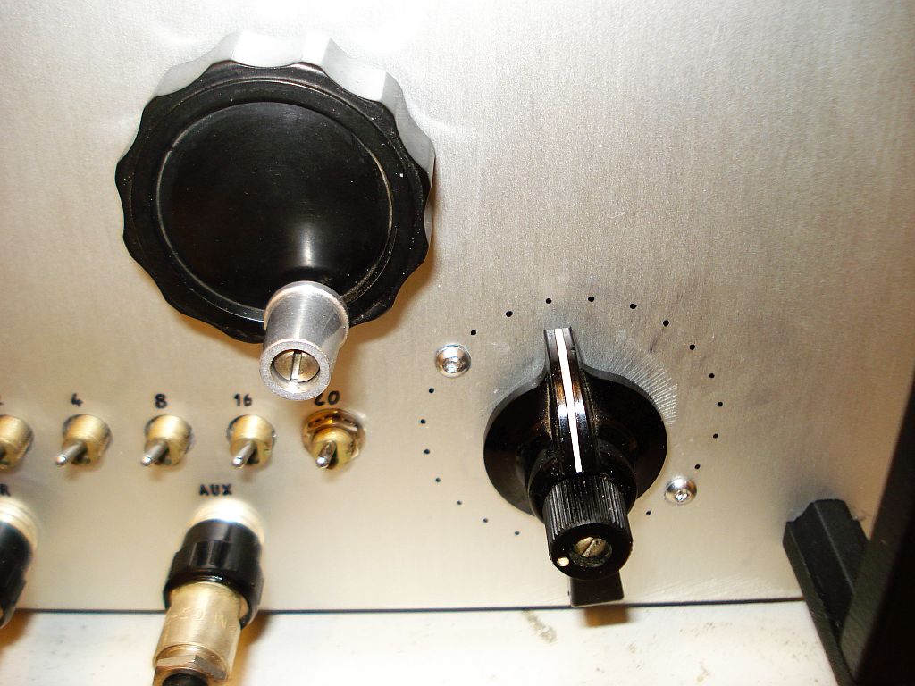
For the average home lab, the main characteristics that distinguish a good analogue RF signal generator from a poor one, as far as concern the quality of the generated signal, are:
- Wide frequency range.
You certainly want a wide frequency range so you can test more circuits
in more frequencies. The widest the better, that is the main purpose
you are making the signal generator. However, keep in mind that as the
frequency gets significantly higher, the frequency stability suffers
more and the need for better shielding gets important.
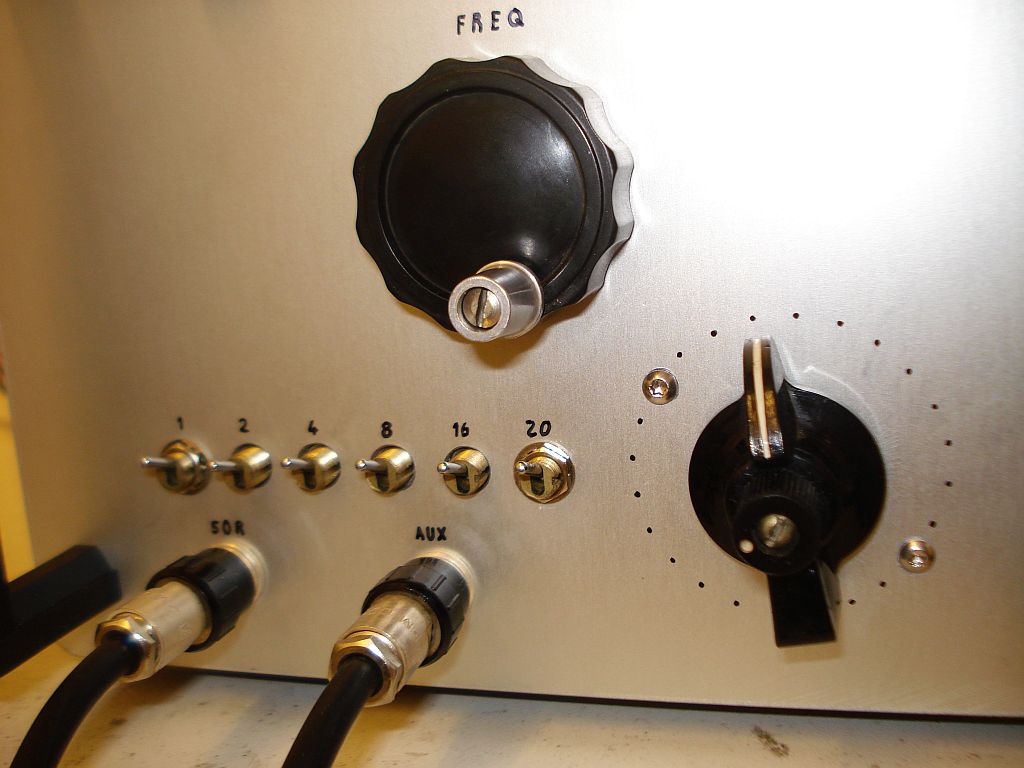
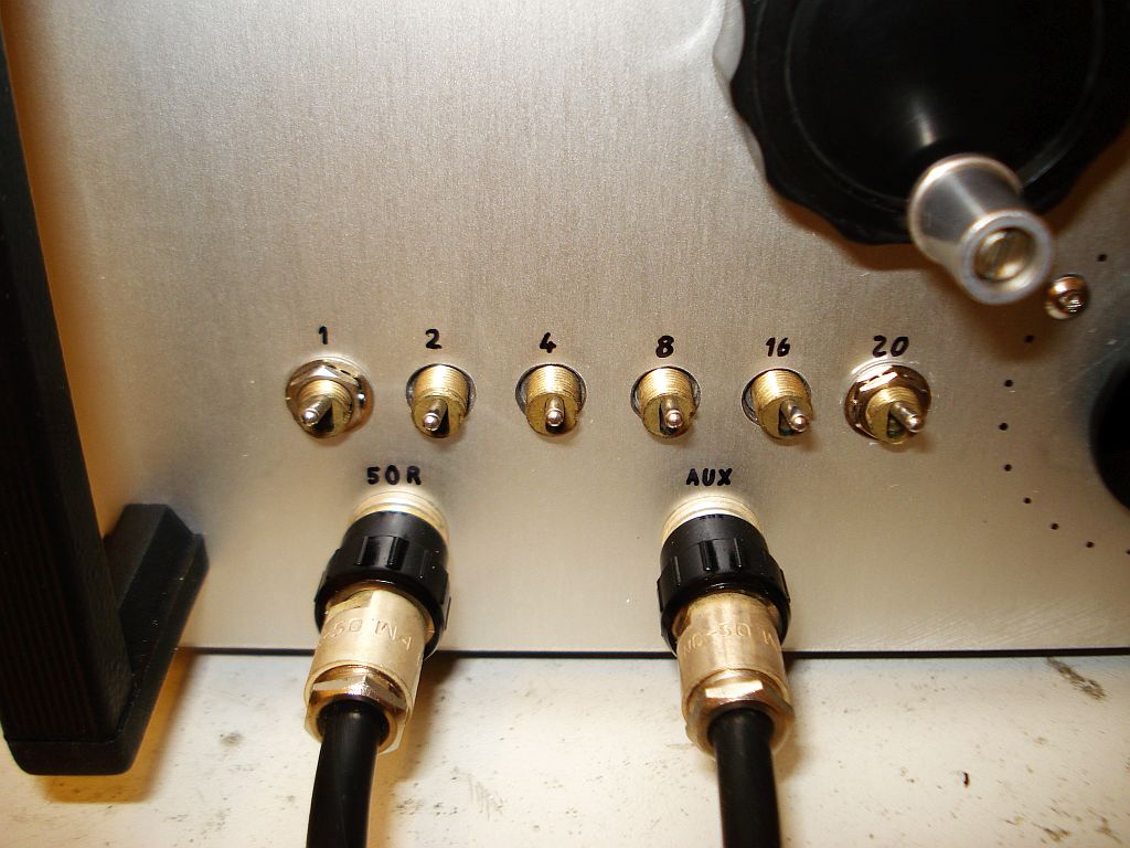
- Variable output level.
The output level of the generated signal must be able to be varied over
a broad range, so that you can test equipment at both very low and high
levels. This is usually accomplished with a resistive attenuator at the
output of the signal generator. This attenuator is better to be a
switched attenuator and not just a potentiometer (voltage divider), so
that the exact attenuating values are known and the input and output
impedances are kept constant regardless of the attenuator setting.
- Constant output level.
If you use an output attenuator, you could set the level of the
generator at any value you wish. However, a constant output level from
the generator (prior to the attenuator) is desirable. This is because,
regardless of the attenuator setting, you would expect in many of your
tests to see a constant output level as you tune accross the frequency
of the generator, regardless of it's level. Imagine for example that
you want to sweep the generator to test the responce of a wideband
filter. The last thing you want, is for the generator level to change
as you sweep across the filter bandpass.
- Constant 50 ohms output impedance.
The output impedance of
the RF generator must remain constant near 50 ohms at all frequencies,
which is the standard impendance value of most of the RF circuits we
use today. It is sometimes ok to drive a higher impedance load with a
50 ohms source, but the opposite may cause problems from the excessive
loading of the generator. The constant impedance must be maintained at
the different settings of the output attenuator (if you use one). A
switched attenuator designed for 50 ohms, fulfills this requirement.
- Low distortion (harmonics content).
Every oscillator, even sinewave, produces harmonics (distortion). In
the case of single band oscillators, these harmonics can be very
easilly attenuated with a low pass filter at it's output. However, in
wideband oscillators, harmonics attenuation cannot be easily and
cheaply done using multiple low pass filters for the different ranges,
so harmonics handling
has to be taken care from the core design of the oscillator and the
buffer amplifiers. It is important to have low distortion, the lowest
the better, especially if you intend to use the RF generator as a local
oscillator to mixers in direct conversion receivers.
- Adequate frequency stability.
This is very important and most unlocked (VFO) analogue RF generators
are not capable of adequate frequency stability. You want your output
signal frequency to stay put for as long time as possible if you want
to do jobs like testing narrow band filters and many others. It is
difficult to achieve that in an unlocked VFO, without an oven to keep
the temperature stable. However, you can minimize frequency drift by
using better quality inductors and capacitors as frequency determining
components and NP0 capacitors in the RF places of the circuit.
Frequency drift compensation using different PPM capacitors is possible
but this is difficult if different resonators are switched in the
circuit.
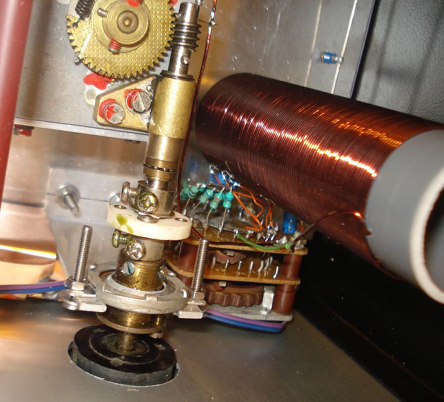
- Fine tuning step
I have seen quite a few wideband RF generators that use just a single
variable capacitor without any reduction gear to set their frequency.
This is ok for general receiver alignment, but for narrow band work
(eg. SSB and CW filters alignment), you need to be able to precisely
set the frequency. In other words, you need to have a fine "tunning
step" if you cant to call it like this, since there is no such thing in
analogue terms. If a variable capacitor is used to vary the frequency,
fine tuning step can be accomplished with the use of mechanical
reduction drives. If very fine tuning step is required, you can even
connect two such drives in series.
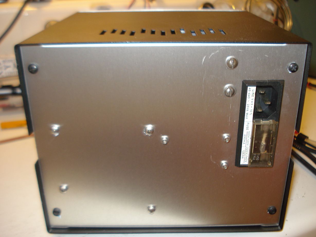
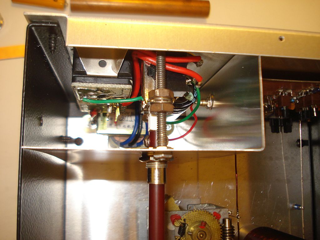
- Good shielding
Good shielding is mandatory to a good quality RF signal generator.
Shielding ensures that frequency pulling from hand effects is
eliminated when you come close to or touch any of the chassis and knobs
in the front panel of the generator. It also provides isolation within
the generator. If you use a switched attenuator make sure you shield
it, so no external signal can pass through it. If you want to go
extreme, each attenuator switch of the attenuator can be independently
shielded from the others. The high voltage and the transformer that
supplies power to the generator must be shielded from the rest of the
circuit as well. You can also use RFI filters in the mains, to prevent
the mains cable from radiating RF leaked from the generator. The whole
RF generator circuit must be enclosed inside a metal enclosure and
connected to ground, but do not place air-core inductors too close to
the metals if you can.
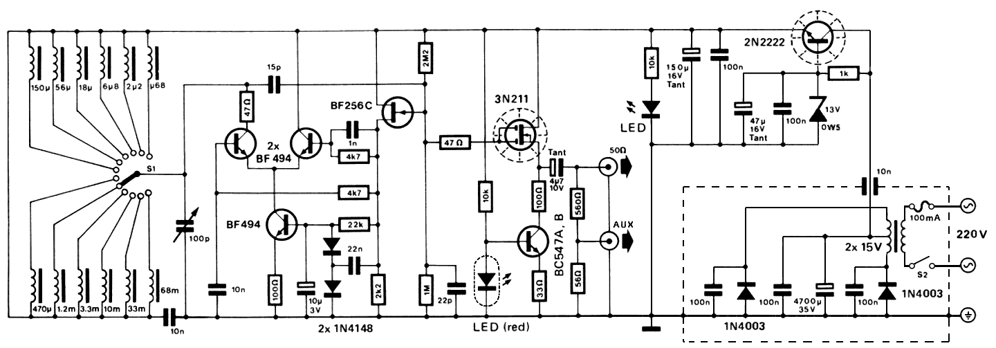
This RF generator was presented in Elektor magazine summer circuits July-August 1980 at page 19.
The schematic above, shows my modifications (not many) and this is
exactly the schematic I built. I have built this circuit in different
versions at the
past and I was satisfied, but this version presented
the best quality signal. The harmonics of the sinewave are -40dBc or
better at all frequencies in this version. I did not build the AM
modulator because I did not like the idea of modulating directly the
oscillator. After all, modulation is only 30% that way. If I needed AM
modulation I would do it better in a later stage, possibly in the final
amplifier.
The power supply is my design. I happened
to have a center tapped transformer so I made the power supply around
this transformer. However, you can use a common 15v transformer and
rectify the AC using four diodes in a bridge configuration instead. In
that case you would need four 100nF capacitors, each placed in parallel
to each diode on the bridge. The regulator is a capacitance multiplier
circuit that has low noise and works well. The 13v zener gives an
output voltage of 12.4v which is very close to the nominal (12v).
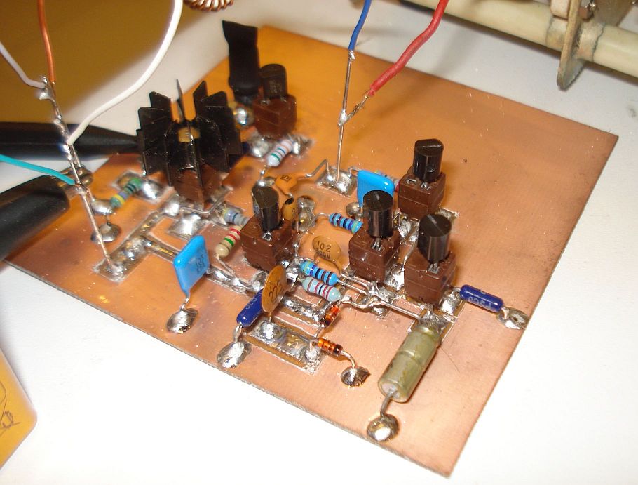
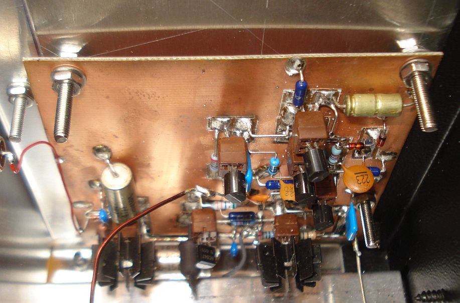
The built style I used was also a new
one. This time I built the circuit on a piece of PCB with all the
components surface mounted. I used a small cutter to cut channels onto
the PCB copper, creating that way the pads and the PCB traces. This method takes a bit more time than
just soldering the components in "dead bug" style, but the result is
very neat as you can see from the pictures.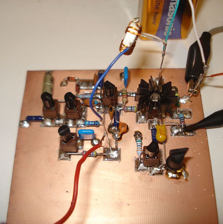
The trick
for quickly engraving channels onto the pcb, is to make thin side lines
on each trace or pad first, making sure that the copper is cut all the
way through, down to the fiberglass. Then peel a small part of the
copper out of the pcb at one side of the trace. Finally, use tweezers
to pull this peeled part and the copper will be pulled all the way
along the channel, isolating the trace from the copper ground around it.
Make sure
you cover the red LED with a small piece of black thermal shrink tube,
so as to create a lightproof enclosure for the LED. Heat the thermal
shrink tube and when it is still hot, hold it's both ends with pliers
and let it cool as you hold it. When it is cooled the shrink tube will
stay in place with both ends closed, preventing any light from affecting the
LED.
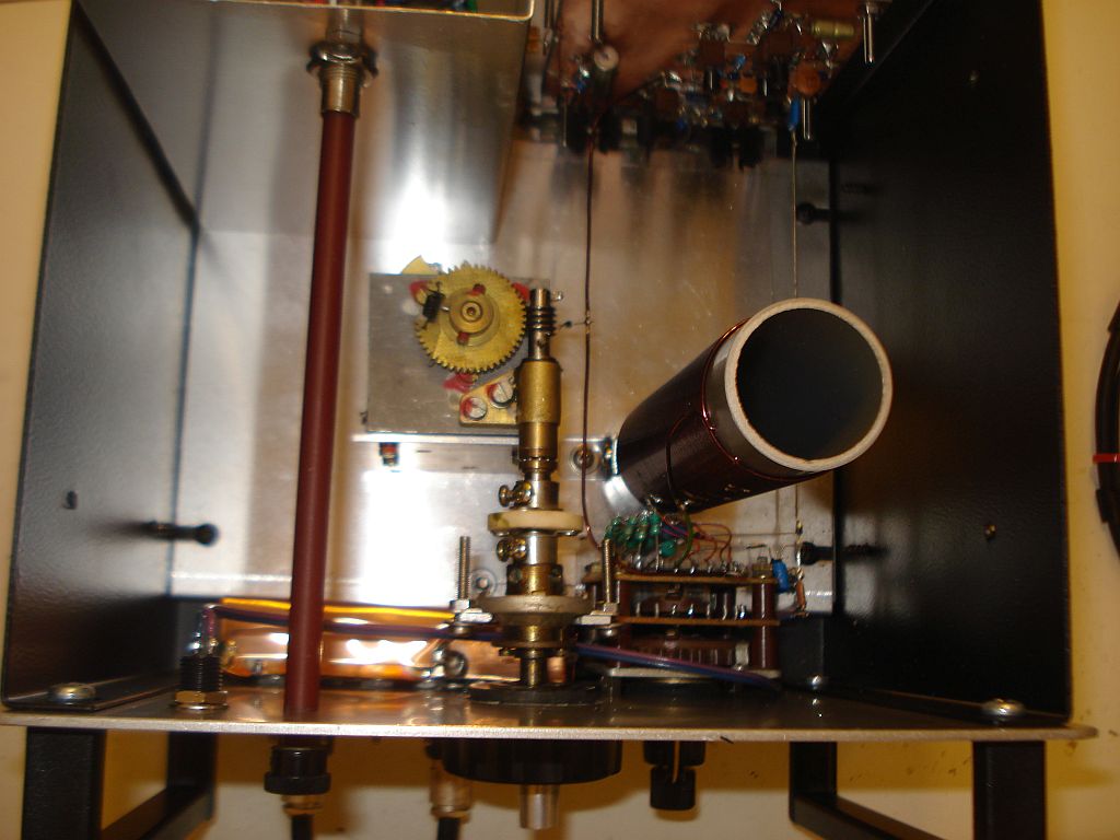
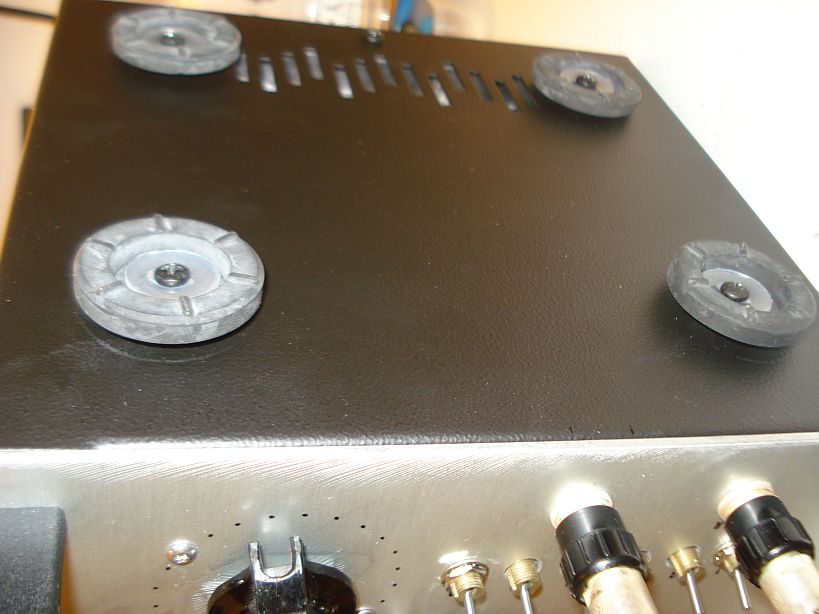
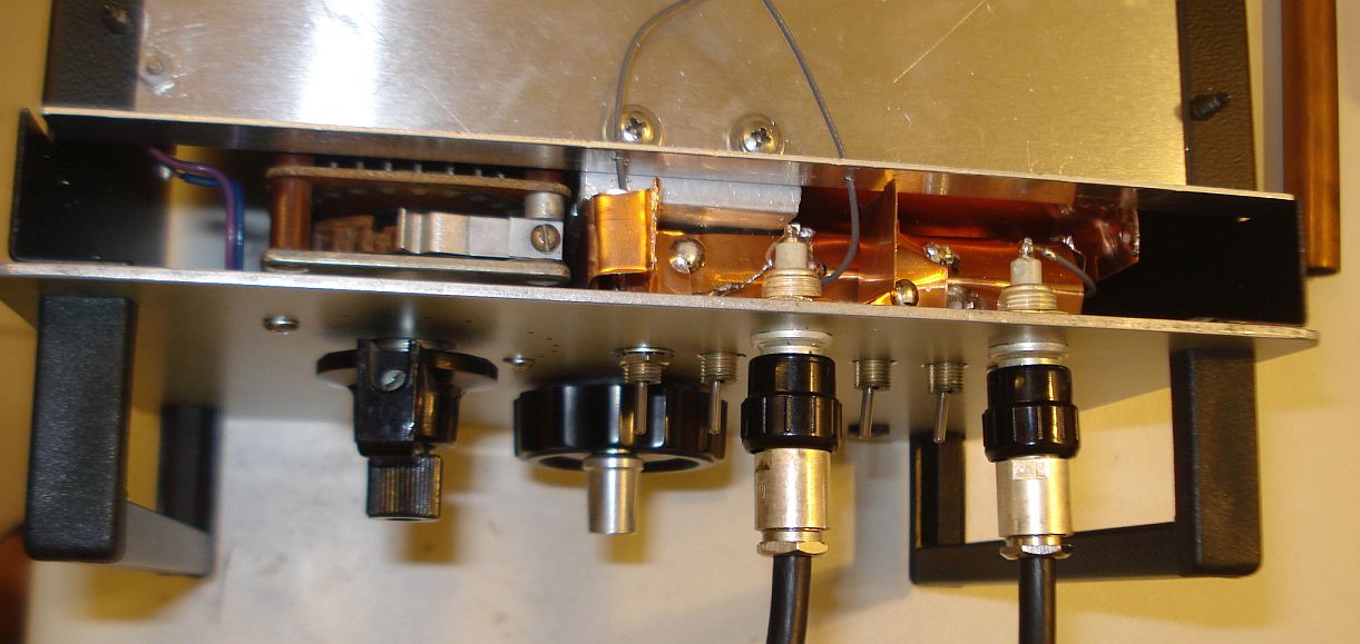
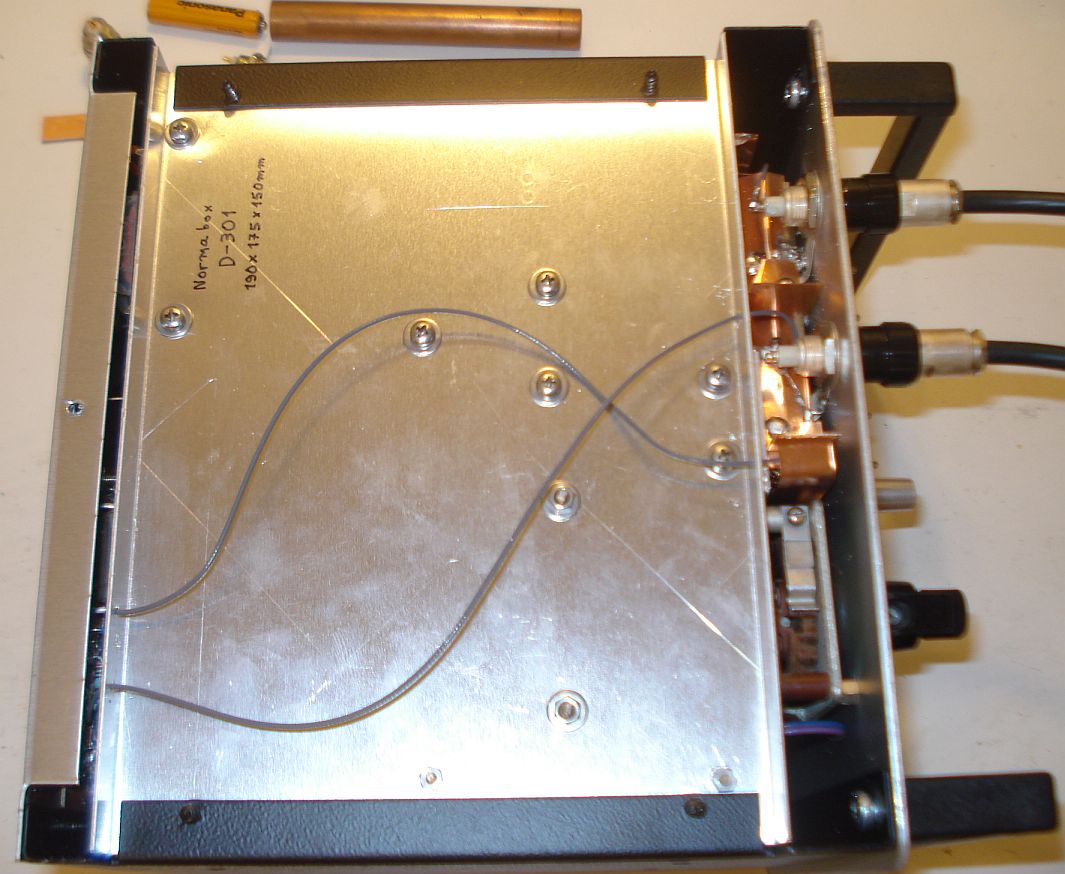
Here are more pictures from my implementation of the RF generator
Back to main
site