A handheld multi-purpose meter for the HF
experimenter
by sv3ora
About the project
During
my experiments in HF RF electronics I usually find myself in situations
where I need to test some of my circuits with simple test equipment.
How simple? Simple enough to do the job, yet quick and easy to build
and cost effective. Usually, such equipment is made for the purpose and
then dissasembled, or lying around somewhere and then I do not know
where it is when I need it again. That is why I have decided to pack
such circuits in a single enclosure, to build a simple multi-purpose
meter.
Enclosure
Before starting this project, a suitable enclosure must be made.
Because this is intended to be a meter with an analogue scale, a
sensitive analogue meter is required, and also a suitable enclosure to
fit the meter and the controls. This enclosure needs to be handheld as
well. There are not many options in my local electronics market for
such an enclosure, but even if there were, the whole thing would
probably cost quite a lot. The cheapest solution was to buy an old
analogue multimeter and keep it's enclosure and meter for the project,
then put apart the internal electronics and it's controls. I bought
such a multimeter new for 6 Euros from a local electronics shop. You
would certainly spend much more if you have to bought the separate
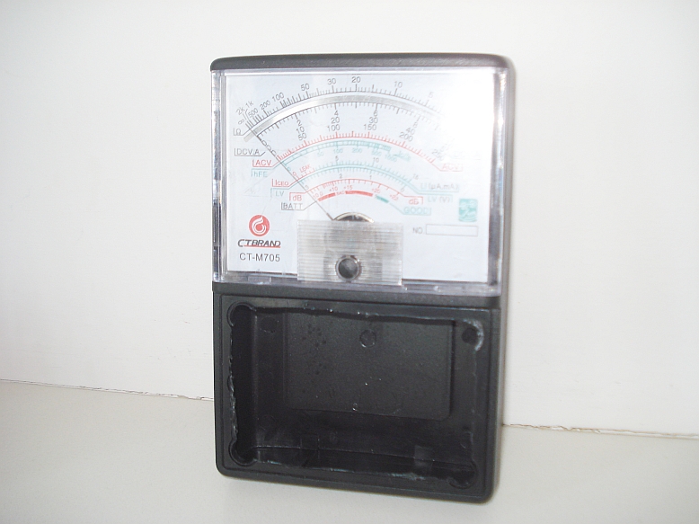
components and join them together. Below, is the multimeter I have
bought.
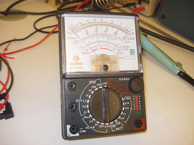
This
is a classic cheap analogue multimeter. It even includes space for a 9v
and a pair of 1.5v batteries inside, so a small PSU could be easily
implemented inside the meter.
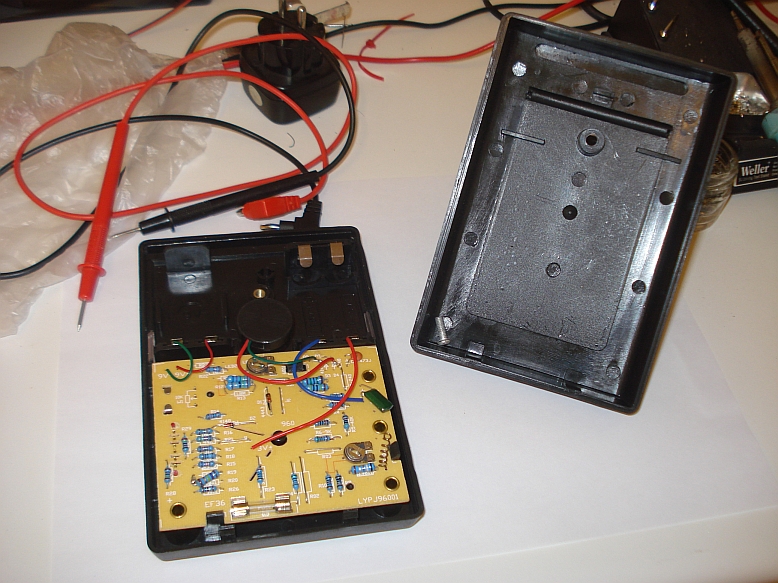
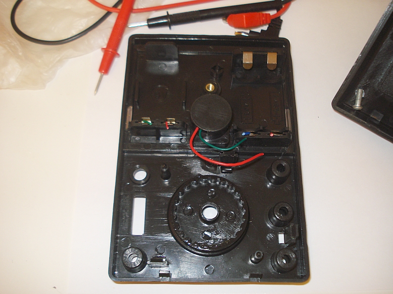
The
internal components were put apart, to leave space for my circuit.
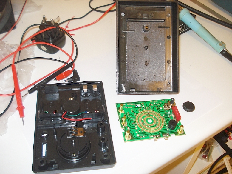
The
front panel and rotary switch were also put apart.
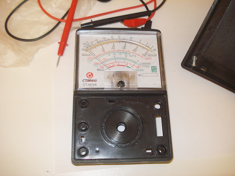
The
front cover plastic of the old multimeter was cut, so that space is
left for the front panel of my custom meter.
A
suitable aluminum sheet was cut in size, to be used as a support for
the front panel components. Select a thin sheet of aluminum, to be able
to cut it easily using a pair of scissors, but thick enough to provide
mechanical stability for the front panel components.
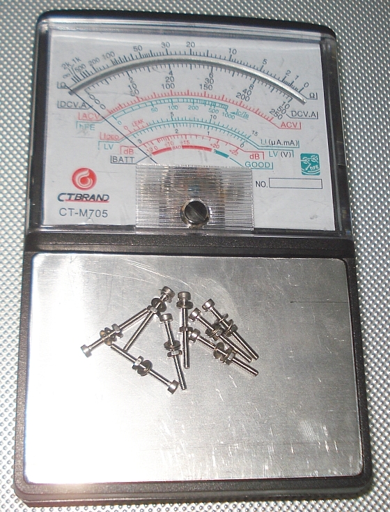
Make
the appropriate holes onto the aluminum sheet and the plastic of the
old meter below it. Then fit the sheet to the meter, using a set of
screws.

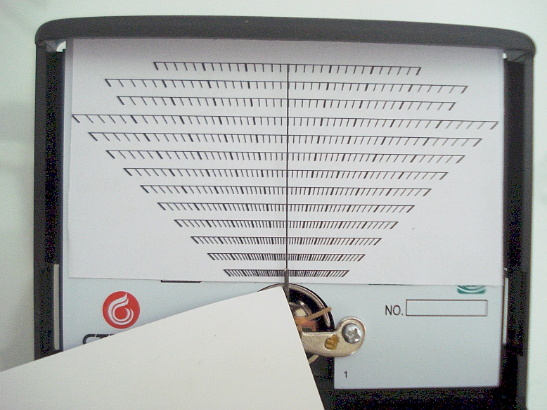
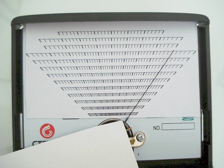
After
finishing with the front panel support, a suitable meter scale has to
be made. The old multimeter had a curved meter scale that followed the
meter needle. This is ok, but it is more difficult to draw custom
curved meter scales and draw the markings onto them in angled
positions. Thus, I have chosen to use a linear scale, which is much
easier to draw and the markings are not drawn in angles.

Click here to download the
scale pattern
of the meter. It is a 14Mb bitmap, which you have to print in scale for
your meter. For my meter, I opened it with infranview and printed it in
custom size of 8.5x6.46. Note, that I have designed the pattern for my
own meter, but you may wish to do changes for your meter, that is why I
provide
you with this pattern as a starting point. After printing the scale,
you have to align it to your meter, so that the center of the scale is
alligned all the way up with the needle and the needle is correctly
aligned at it's extreme movement positions with the scale.
The use of the linear scale has the disadvantage that because of the
circular motion of the needle, the linear scale expands towards the
ends. However, this does not seem too much of a disadvantage for my
purpose, having in mind that the rate of change of the needle motion is
not linear anyway. Also, the final step lines that are shown in the
preliminary scale below, will probably change positions, depended on
the actual calibration of the instrument.
Another
point, is that the representation of the circular motion of the meter
onto a linear scale, leaves some "empty space" at the top of the scale.
I thought of taking advantage of this space , so I plotted three more
scales at the top of the meter, which do not start from zero and end at
the full scale reading. These could be useful only in circuits where
starting and ending positions do not matter, for example in relative
measurements or deviation-from-zero measurements.
Because
of the representation of the circular motion of the needle onto a
linear scale, the needle cannot extend all the way up to the top, at
the scale ends. This is not much of a problem, since one can easily
virtually extend the needle, as shown above.
Power supply
The first thing I wanted to include inside this meter, was a small
integrated power supply. There are many times where I need a power
source for my circuits and the only available one, is the big and bulky
lab PSU or external heavy batteries. Not only that, but sometimes I
need more than one voltage simultaneously. For example a higher power
source to feed a QRP transmitter amplifier and also, a tiny power
variable voltage source, to tune the varactor of the oscillator section
of the transmitter. I usually end up in external potentiometers or
variable regulators to do the job. A more permanent, portable and
versatile source of power is thus necessary.
|
|
|
|
|
|
|
|
|
onoff1 |
|
|
|
|
|
|
|
|
|
|
|
|
 |
 |
|
|
 |
 |
|
|
|
|
 |
term1 |
|
|
|
|
|
|
 |
|
|
|
|
|
|
|
adj |
 |
|
|
|
|
|
|
|
|
|
100k |
|
12v |
 |
|
|
|
|
 |
|
|
|
|
|
|
|
|
 |
 |
 |
|
|
100k |
 |
|
500r |
 |
|
|
|
|
|
|
|
|
|
|
|
|
|
|
 |
|
|
 |
100k |
|
|
|
| term4 |
 |
|
|
 |
lm317 |
 |
3mm |
|
3mm |
|
|
|
|
|
|
|
term2 |
|
|
|
240r |
|
|
|
|
|
|
|
 |
|
|
10k |
|
|
|
|
|
|
|
|
|
|
|
|
|
|
|
500r |
|
|
|
|
|
|
1uf |
 |
|
 |
5k |
|
onoff2 |
|
|
|
|
|
|
|
|
|
|
|
|
|
 |
|
|
|
|
|
|
|
|
|
|
|
term3 |
|
|
After a bit of thought, I
ended up in a small, cheap but versatile PSU design, shown above. The
PSU, is used to power external circuits, as well as circuits internal
to the meter. The
main power source, is a battery internal to the meter. The meter has
two positions, one for a 9v battery and one for a pair of 1.5v
batteries. I have not yet decided if I will keep these, or replace these with a series AAA holder (to be determined)
The PSU can be used in different configurations:
1. When "onoff1" is on, term1 is at +12v and term3 at 0v and they supply the full battery current.
2. If one conencts the term1 to the gnd of a circuit to be powered,
then term3 can be connected to the -12v (useful for PNP circuits).
3. When "adj" is closed the two potentiometers coarse and fine tune the
low current positive voltage on term2 (useful for tuning varactors). At
the same time, term1 supplies +12v at full current.
4. If "adj" is closed and reverse connections are done, like mentioned
in point 2 above, then term2 will present a negative variable voltage
and at the same time, term3 will present a full current of -12v.
5. If the GND of the circuit to be powered is connected to term2,
then this can be used as a low current split rail PSU, providing term1
with +6v and term3 with -6v. The potentiometers can set the balance of
the supply then. I am not sure what is the effect of the 100k and 10k
series resistros in that case though.
6. Because higher current with adjustable voltage may also be needed,
an LM317 is added. This can work in parallel to the rest of the
circuit, providing an extra high power variable voltage source, but not
when the split supply configuration is used, unless two independent
circuits are to be powered. Also if
reverse polarity is used at the right hand section of the circuit, one
has to manually take care not to short the two sections grounds
together, unless they are electrically isolated. That is why the
addition of the onoff2 switch thought to be better at the gnd side of
the regulator.
Low current LED indicators, show which section is on/off. There are numerous times
where you forget circuits to ON and they drain the battery. So despite that being
silly, thought to be very useful indeed.
To be
continued...
Back to main site