
Poor
man's HF spectrum analyzer
Introduction
This spectrum analyzer has been designed for ultra low cost and easiness of construction, to satisfy some of the needs of the HF experimenter. Of course, extreme performance should not be expected from such a simple circuit. However, care has been taken, so that despite it's simplicity, it's performance is not very much compromised and a useful instrument is produced. As mentioned, cost and easiness of construction was more important than extreme performance.
Block diagram
The overall preliminary block diagram of the spectrum analyzer is shown below.
 |
|
|
|
|
|
|
|
|
|
|
|
|
|
|
|
|
|
|
|
|
LPF | |
|
|
|
|
|
|
|
|
|
|
|
|
|
|
|
|
 |
|
ATT | |
MXR | |
BPF | |
AMP | |
DET | |
|
|
PC (SB) |
| IN |  |
|
|
|
|
 |
|
|
|
|
|
|
|
 |
OUT | |
 |
|
|
|
|
|
|
|
 |
|
|
|
|
|
|
|
|
|
 |
|
|
|
HPF | |
|
VCO | |
|
|
|
|
|
|
|
|
|
|
|
|
|
|
|
|
|
|
|
|
|
|
|
|
|
|
|
|
|
|
|
|
|
|
SWP | |
|
|
|
|
|
|
|
TRIG OUT |
|
 |
The input signals pass through a selection of LPF or HPF, to select the 0-15MHz and 15-30MHz signals respectively. These front end filters, also provide the RF front end image rejection. Then a stepped attenuator feeds the desired signals to a mixer. The mixer is driven by the 0-15MHz VCO, which is swept by the sweeper. The sweeper also provides the trigger signal to the scope or PC. The mixer is followed by a 15MHz BPF, to reject unwanted mixer products and the signal after the filter is amplified, detected and the output is fed to the scope or the PC.
This single conversion spectrum analyzer does not use a high-IF, but instead the IF resides right in the middle of the coverage frequency of it. This has been done for several reasons.
First, the post mixer filter is a limiting factor in the design of a spectrum analyzer. We want an overall spectrum analyzer that will be simple to build, so helical filters are out of question. On the other hand, for high resolution, no other component can beat a single quartz crystal filter. But fundamental mode quartz crystals are produced for frequencies of less than 20MHz or so. A 15MHz IF, is well inside this limit. In a dual conversion spectrum analyzer the first IF is higher than the spectrum analyzer coverage, but this requires the use of complex and expensive first IF filters and additional second IF filters. A single conversion design seems better to be employed if simplicity and cost is the goal, but the the IF frequency bust be carefully selected.
Second, the local oscillator used, is able to provide good performance up to about 15MHz. Above that, it's performance gets worst. Instead of limiting the useable range of the spectrum analyzer to 15MHz, we can use the mixer to double that range, by using the addition mixer products as well. Thus, with a 0-15MHz local oscillator, we can cover double this bandwidth, if suitable RF frond end filters are used. That is 0-30MHz, just enough to cover the whole HF.
Of course, by using 15MHz as IF, some of the bandwidth close to 15MHz cannot be effectively monitored. But anyway, the local oscillator coverage, does not actually start from 0Hz, as mentioned above for simplicity, but from about 20KHz. So either way, 20KHz below and above 15MHz cannot be monitored. However for the purpose of the radio amateur, this may not be much of a problem, since the last frequency on the 14MHz band is 14.350MHz and the first frequency on the 18MHz band is 18.068MHz, so these bands can be effectively monitored.
SWP
The sweeper is a reverse sawtooth generator. It's output drives the VCO varicap directly. The frequency is changed by switching Cx. Starting values for Cx are 100nF, 1uF, 2uF etc.
|
|
|
|
|
|
|
|
|
|
|
|
|
|
+12v | |
|
|
|
|
|
|
|
|
|
|
|
|
|
|
|
 |
|
|
|
 |
|
 |
|
|
|
|
|
|
|
|
|
|
 |
|
|
| 10k |  |
2n2907 |  |
|
 |
|
|
|
|
|
|
|
|
|
|
|
|
 |
|
 |
|
 |
2n2222 | |
|
|
|
|
|
|
|
|
|
| 2,2k | |
|
|
1n4148 |  |
|
|
|
|
|
|
|
|
|
|
|
|
 |
|
|
|
|
|
|
|
|
2n2222 | |
|
|
 |
2n2907 | |
|
|
|
|
56k | |
|
 |
Cx | |
|
|
|
2n2222 | |
|
|
|
|
|
|
|
|
|
|
|
|
|
|
 |
|
|
|
Vout |
|
|
|
|
|
|
|
|
|
 |
|
|
100k | |
|
|
|
|
|
|
|
56k | |
|
|
|
|
|
|
|
|
|
|
|
|
|
|
|
|
|
|
|
|
|
|
|
|
|
|
|
|
Despite the simple schematic, the sweeper outputs a low distortion reverse sawtooth waveform to the VCO. The rising edge of the reverse sawtooth waveform is also used as a trigger pulse to the scope display.
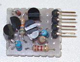
In the sweeper prototype above, starting from the top to the bottom, the pins are defined as:
Pin 1:
Cx (positive)
Pin 2: +12v
Pin 3: Vout
Pin 4: GND
VCO
This simple low distortion sinusoidal VCO, presents a quite constant amplitude throughout all bands from about 20KHz to 15MHz. The VCO range can be extended much higher, but the amplitude is not constant at higher frequencies.
|
|
|
|
|
|
|
|
|
|
|
|
|
|
|
|
|
|
|
|
|
|
|
|
|
120 | |
Lx | |
|
|
|
|
|
2.2M | |
|
|
|
|
bf256 | |
|
|
|
|
| +12v | |
 |
|
|
|
|
|
|
|
|
|
|
|
|
|
|
|
|
|
|
|
|
|
|
7.2v |  |
 |
|
|
47 | |
|
100pF | |
|
1nF | 47 | |
|
 |
 |
bf256 | |
|
|
|
|
|
|
|
|
|
|
|
|
 |
|
|
|
|
|
|
|
|
100nF | |
|
|
|
|
100k | Cx | |
|
bf494 | |
bf494 | |
|
|
|
|
|
|
|
|
|
|
|
|
Hout |
| Vin | |
|
|
|
|
|
|
|
 |
|
|
|
|
|
|
|
|
|
|
|
560 | |
|
|
|
1sv149 |  |
|
|
|
|
|
|
4.7k | 4.7k | |
|
1M | |
|
|
|
|
|
Lout |
|
|
|
|
|
|
|
|
|
|
|
|
|
|
|
|
|
|
|
|
|
56 | |
|
|
|
|
|
|
|
bf494 | |
|
|
|
|
|
|
22k | |
22pF | |
100 | |
|
|
|
|
|
|
|
|
|
100 | |
10uF |  |
1n 4148 |
|
22nF | |
|
|
|
|
|
|
|
|
|
|
|
|
|
|
10nF | |
|
|
|
|
|
|
|
|
|
|
|
bc547 | |
|
|
|
|
|
|
|
|
|
|
|
|
|
1n 4148 |
|
2.2k | |
|
 |
LED | |
33 | |
|
|
|
|
|
|
|
|
|
|
|
10k | |
|
|
|
|
|
|
|
|
|
|
|
|
|
|
|
|
|
|
|
|
|
|
|
|
|
|
|
|
|
|
|
|
|
|
|
Lx is a switched coil which sets the band of operation. The range of the spectrum analyzer within each band, can be set with a voltage divider potentiometer, with it's taper connected to Vin. Cx is the span capacitor. With Cx around 100nF and Vin connected directly to the sweeper without a voltage divider, the band span is at maximum and the oscillator covers the next frequencies:
| Lx | Frequency range | Output power variation @ 1Mohm |
| 68mH | 27.07-83.16KHz | 528-609mVpp |
| 10mH | 74.56-230.92KHz | 503-584mVpp |
| 1.5mH | 185.17-554.94KHz | 496-590mVpp |
| 220uH | 494.85khz-1.502MHz | 471-587mVpp |
| 22uH | 1.599-5.125MHz | 446-631mVpp |
| 2.2uH | 4.745-15.643MHz | 356-709mVpp |
To make it more clear, the procedure of tuning the spectrum analyzer into a signal is summarized below:
Set Lx to cover the band of interest.
Set Cx to maximum (100nF) and the potential divider to maximum resistance to the ground (maximum voltage on Vin). Your signal will be displayed somewhere in the screen.
To zoom into the signal:
Reduce Cx, so that the span is decreased. This span decrease, will also cut off the lower frequencies in the band, so your signal may be lost for a while from the screen, if it is at the lower end of the band.
Retune the voltage divider until you find your signal again. Decreasing the resistance of the potential divider to the ground means that the sweeper voltage fed to the Vin, will be decreased. This decrease, forces the VCO to operate at lower frequencies
Obviously, the range and the span settings, affect each other. When you change the span, you have to retune the range and vice versa.
BB112 can be used as a direct replacement to the 1sv149. The VCO provides two outputs, a high impedance and a 50 ohm one.
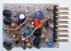
In the VCO prototype above, starting from the top to the bottom, the pins are defined as:
Pin 1:
+12v
Pin 2: Zener cathode point
Pin 3: Connection point of Cx and Lx
Pin 4: GND
Pin 5: Vin
Pin 6: Connection point of Cx and varicap
Pin 7: Lout
Pin 8: Hout
MXR
The
mixer is a Gilbert cell type, made out of discrete components. This
type of mixer is broadband and does not require complex transformers.
At the same time, since this is a double-balanced mixer, the carrier is
attenuated at the output, so you do not have to deal with a strong
carrier signal that might affect other stages of the spectrum analyzer,
at least in theory. In practice, if the local oscillator frequency
changes quite a lot, the carrier nulling potentiometer has to be
readjusted. This is of course not too practical in this project.
|
|
|
|
|
|
|
|
|
|
|
|
|
|
|
|
+12v | |
|
|
|
|
|
|
|
|
|
|
|
|
|
|
|
|
|
|
|
|
|
|
|
|
|
|
|
|
|
|
|
|
LOSC In |
|
|
|
|
|
|
|
|
|
|
|
470 | |
|
|
|
|
|
470 | |
|
|
|
1uF | |
|
|
|
|
|
|
|
|
|
|
|
|
|
|
|
|
|
|
|
|
|
|
|
|
|
|
|
|
|
|
|
10nF | |
|
|
|
|
|
|
470 | |
|
|
|
2n2222 | |
|
|
|
|
|
 |
|
|
|
Out |
|
|
|
|
|
|
|
|
|
|
|
2n2222 | |
|
 |
2n2222 | |
|
|
|
|
|
| 47uF | |
|
100nF | |
|
|
|
|
|
|
|
|
|
|
|
|
|
2n2222 | |
|
|
|
|
|
|
|
470 | |
470 | |
|
|
|
|
|
|
|
|
|
|
|
|
|
|
|
|
|
|
|
|
|
|
|
|
|
2n2222 | |
2n2222 | |
|
|
|
|
|
|
| 47uF | |
|
100nF | |
470 | |
1uF | |
|
|
|
|
|
|
|
|
|
|
|
|
|
|
|
|
|
|
|
|
|
 |
5k |  |
|
|
|
470 | |
|
|
|
|
|
|
|
|
|
|
|
|
|
|
RF In | |
|
|
|
|
470 | |
|
|
|
|
|
|
|
|
|
|
|
|
|
|
|
|
|
|
|
|
|
|
|
|
|
|
|
|
|
|
|
|
|
|
|
|
|
|
|
|
|
|
|
|
|
|
|
|
|
|
To
adjust the mixer, connect the local oscillator to the LOSC input and
adjust the 5k potentiometer for minimum carrier output at the Out port
of the mixer. However, as said earlier, this potentiometer has to be
readjusted if the local oscillator frequency changes too much, so try
to find a setting where the attenuation of the carrier is as high as
possible in all frequencies.
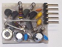
In the mixer prototype above, starting from the top to the bottom, the pins are defined as:
Pin 1:
+12v
Pin 2: Out
Pin 3: RF In
Pin 4: LOSC In
Pin 5: GND
The
mixer was tested by feeding the sweeped local oscillator signal to it,
at a low sweep rate and noticing it's output on another spectrum
analyzer. The local oscillator and it's harmonics appeared to sweep on
the spectrum analyzer display. Then another signal from a low
distortion (harmonics-free) crystal oscillator was applied at the RF
input of the mixer. This signl appeared as well on the display and it
did not change frequency along with the sweep. However, other signals
appeared as well on the spectrum analyzer display, which did change
frequency along with a sweep, at a slightly different sweep rate. These
signals are the wanted products of the mixer.
BPF
The band pass filter is actually composed of two band pass filters connected in series. The first wide BPF is a 15MHz LC filter, which attenuates the out of band mixer products. The second narrow BPF, connected after the first one, is a 15MHz single crystal filter, which selects a very narrow portion around 15MHz. The resolution of the spectrum analyzer, is defined by this narrow filter.
 |
|
|
|
|
|
|
|
|
|||||||||||||||||
|
|
|
|
2.2uH | |
|
|
|
|||||||||||||||||
|
input |  |
 |
 |
 |
|
 |
output | |||||||||||||||||
|
|
100nH |  |
|
47pF | |
100nH | |
|||||||||||||||||
|
|
|
 |
|
|
|
|
|
The
schematic of the 15MHz wide BPF filter is shown above. The components
tolerances are quite critical. The capacitor must be of 1% tolerance
(silver mica), or else use a 10-60pF variable capacitor to tune the
filter. The 2.2uH inductor is made with 37 turns on T30-12 toroidal
core. The 100nH inductors are made with 8 turns on T30-12 toroidal
cores.
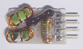
In the wide BPF prototype above, starting from the top to the bottom, the pins are defined as:
Pin 1:
RF out
Pin 2: Not connected
Pin 3: GND
Pin 4: RF in
The schematic of the 15MHz narrow
BPF, will be presented here soon.
Display
Usually, homemade spectrum analyzers, employ an oscilloscope to be used as an XY display. The problem is that the cost gets high, because one needs to have or buy an oscilloscope. The approach I have used, does not use the XY signals but a trigger pulse in conjunction with the detector output signal. A PC sound blaster is used in conjunction with suitable software, to act as the display for the spectrum analyzer. This approach is of ultra low cost, since almost anyone has a PC at home already.
The software used, is the Visual Analyzer, which is a very advanced free sound blaster oscilloscope/analyzer program. As an addition, it provides a voltmeter, a frequency counter, a signal generator, THD meters a ZLCR meter and it is fully configurable.

The software has a very unique feature. One of the two channels of the soundcard input can be set to trigger the other channel. This means that the trigger signal from the spectrum analyzer can trigger the scope display, in which the spectrum analyzer detector output is fed. This allows the output signal of the spectrum analyzer to be displayed without the need for additional AD converter chips (possibly connected to the PC LPT port).
The use of this software, in conjunction with the PC sound blaster, has also another advantage. For frequencies lower than 20KHz, the program may be used alone if wished, without the need for the rest of the spectrum analyzer hardware.
Because of the additional signal generator provided by the program, one of the two channels could be possibly used both to trigger the display and to directly drive the VCO, without the need for an additional hardware sweeper. However the program cannot output sweep rates lower than 1sec (which is needed for high resolution). Also there may be possible incapability of the soundcard to output DC. Thus, this feature has to be yet determined.
To be continued...