Semiconductor analyzer
For BJTs, mosfets and diodes
An Elektor project implemented by SV3ORA
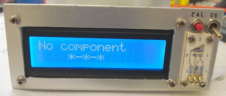
Almost every electronic circuit contains bipolar transistors, FETs or diodes. Most electronics hobbyists have a supply of such components removed from old circuit boards. A tester that can be used to sort out the leads and measure the characteristics is thus a handy tool.
Most of the times I find the transistors leads assortment feature very useful. The analyzer tells me where the base, collector and emitter of the transistor is, so I do need to switch on my computer and look for the particular transistor datasheet.
Original Elektor article
Corrected PCB pdf file
(prints in correct scale)
Firmware for the PIC
(see inside the files, for correct programmer fuses)
The original article has an error on the PCB. The PCB pdf file above, is the corrected version of the PCB. The correction has been taken from a later issue of Elektor, which is shown below.

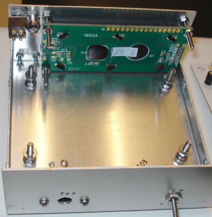
The LCD used, is a standard 2x16 HD44780 compatible LCD module. Watch out, pins 15 and 16 (which are used for the backlight) are on the opposite side of the connector, so some wiring extension should be used for these pins.
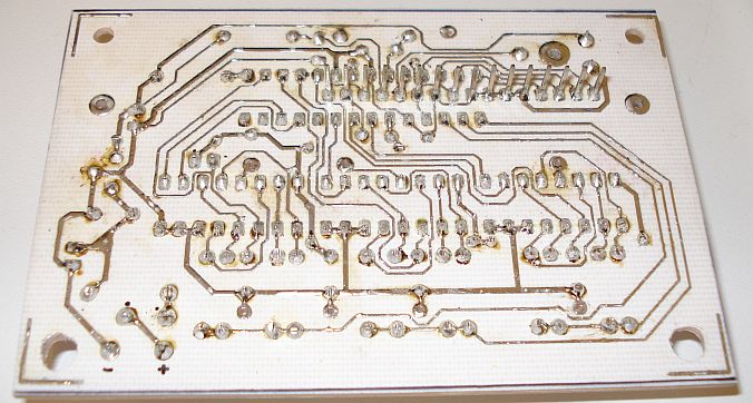
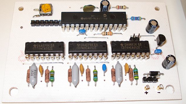
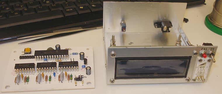
The PCB has been etched and all the components have been fit in. Try to use at least 1% tolerance resistors on the measuring section of the schematic. I used 0.1% in fact, to improve accuracy.
A small case is all that is needed to fit the different external components.
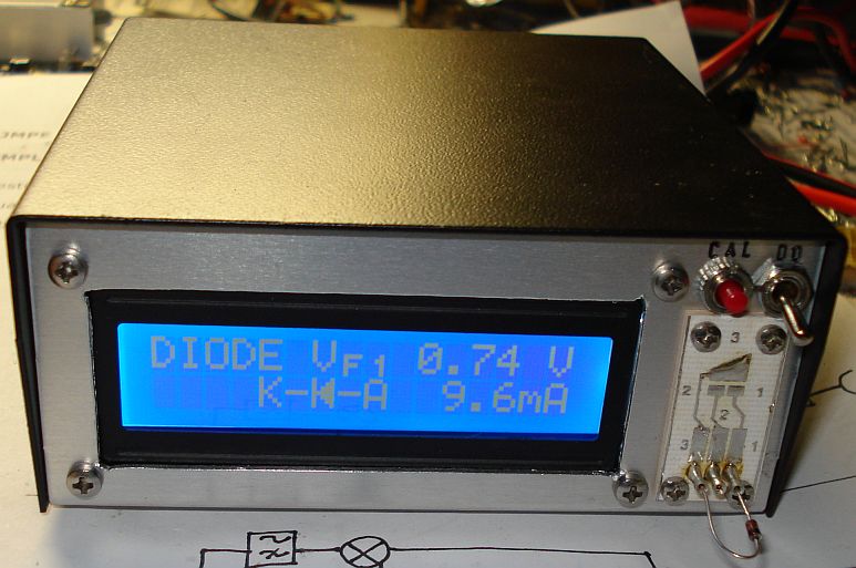
The final arrangement is shown below. A momentary switch is used in place of the jumper and a DPST switch is used to short circuit the three testing leads. These two switches are useful for easier calibration of the analyzer from the front pannel.
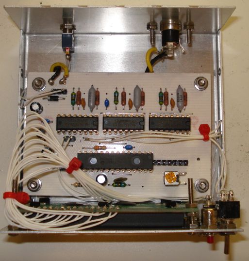
The tester PCB was mounted on the front panel using screws, for easier component testing. On the back side, there is a hole on the aluminum front panel, that allows the three tester pins to pass through it and connect to the analyzer PCB, using small lengths of wires.