by SV3ORA
This page is not complete yet
Preface
An oscillator is the basis of all modern receivers and transmitters. In many circuits the oscillator characteristics (stability, phase noise, frequency range, output level, signal distortion, spectral purity, etc) define in a great extend the overal system characteristics. Designing signal sources has been an issue for many decades and different types of signal generating techniques have been proposed over the years, each one with it's own characteristics.
Basic oscillator types
HF radio amateurs pay specific attention mostly on two basic characteristics of an oscillator, frequency range and stability. The first one, defines the receiving range on a receiver and the transmitting range on a transmitter. The second one, defines the frequency stability of a receiver or a transmitter. Many techniques have been tried in order to achieve such good characteristics. Some of these include:
Obviously, one or more of the above mentioned techniques can be combined, to achieve the desired specifications in a system.
Oscillators spectral purity
Apart from frequency range and stability, there is a third parameter that is important in HF designs and this is the spectral purity of the oscillator. Every oscillator type of the above, will generate harmonics of the fundamental frequency. Especially on mixer and DDS based oscillators, the harmonics and spurious can be so many, that is difficult to calculate them without using an appropriate calculator software. The unwanted harmonics can degrade the system performance so much as to make it totally useless in some applications. The solution is filtering.
Filtering
Filtering of harmonics is easy on VFO, VCO, XO or VXO oscillators. It usually consists of a LPF after the oscillator, to filter the higher produced harmonics. Since the range of these oscillators is limited, just one LPF is usually required per oscillator. However, on synthesized and DDS oscillators, filtering is much more difficult.
DDSs have harmonics as well as totally unrelated spurious tones, that can become huge as you approach an output frequency of around 1/2 the clock rate. Some radio amateurs use DDS as the LO in receivers, but this could have spurii all over the place, so one would probably want to filter as much as possible. This requires many different filters or variable ones which are difficult to make and tune and the unwanted signals could never be totally eliminated. The best solution, if such signals must not be present in the system, is to try not to use a DDS as LO at all.
In synthesized oscillators, fundamental and higher harmonics from both oscillators in the mixer input will combine and produce a wide range of output frequencies, not only higher than the oscillator frequencies, but lower as well. As before, filtering becomes very difficult at the mixer output. At least, in this case, there is something else that can be done to improve things.
The oscillator design
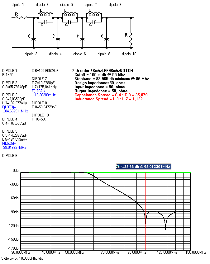
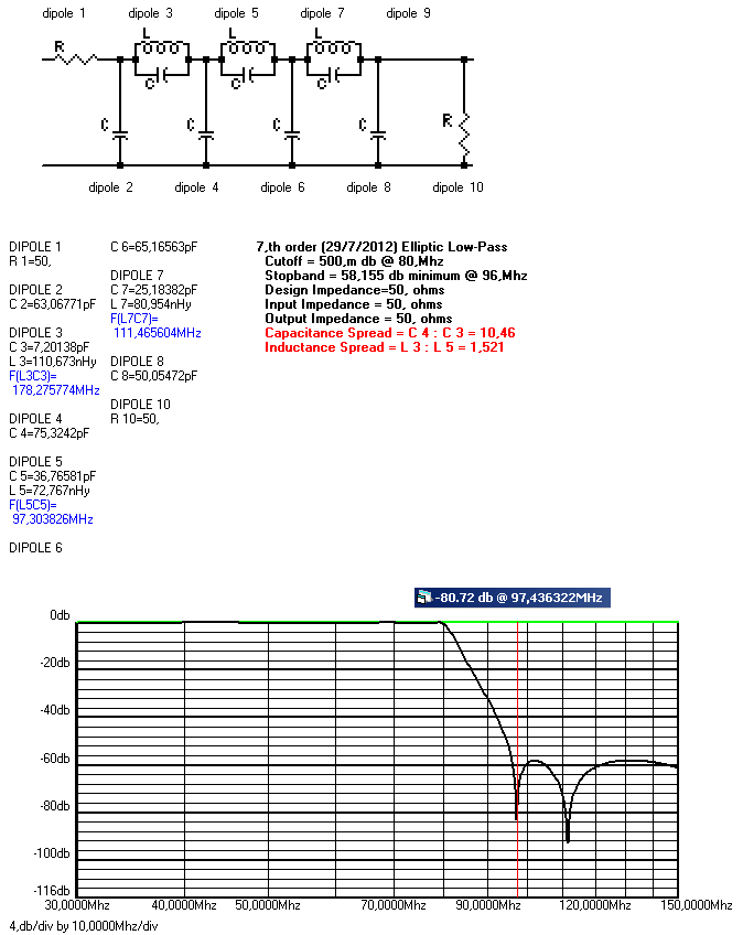
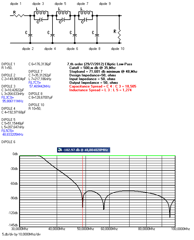
By carefully selecting the frequency ranges of the oscillators, just two suitable low pass filters can be built, to filter out the higher harmonics of the oscillators prior to mixing. Thus, the levels of the oscillators harmonics will be much lower and the mixer output signal will be much cleaner. Nevertheless, a third LPF is needed after the mixer, to filter out unwanted mixer products, as well as further attenuating any oscillators harmonics higher products that have passed the mixer.
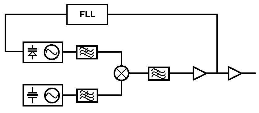
The overal oscillator proposal is shown above. A fixed frequency crystal oscillator is mixed with a VCO to produce the wanted range of frequencies. Filtering is done before and after the mixer. Following the mixer is a set of broadband amplifiers to isolate it from the load and to bring the wanted signal into useable higher levels.
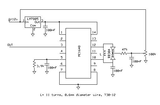
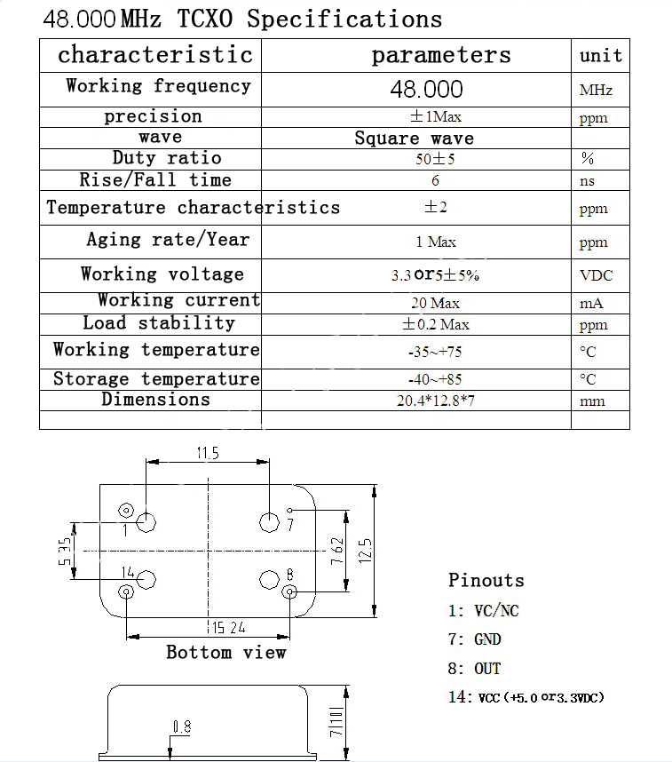
As far as concern frequency stability, the fixed frequency crystal oscillator can be very stable, especially if a TCXO is used. Thus, the main thing that defines output frequency stability, is the VCO stability. Especially if using high frequencies for the VCO, the stability could suffer. Therefore an FFL is used to stabilize the VCO. The FLL chosen, had an embedded frequency counter, so it was connected between the filtered mixer output and the VCO, to directly read and display the output frequency. Alternativelly, if an FLL without a frequency display is to be used, the FLL could be connected between the input and the filtered output of the VCO.
The mixer
The mixer used is a Mini Circuits MCL SRA-6. This has a 3KHz-100MHz LO/RF and a DC-100MHz IF. Detailed specifications about this mixer can be found in this pdf file. If you can't find this mixer an SBL-1 may be alternativelly used with narrower lower range or you may build your own discrete mixer from a quad of diodes and a pair of broadband transformers.
The filters I have designed are shown below.