
by SV3ORA
A simple to assemble regenerative SW receiver
by SV3ORA
Here is a very simple to build, 25 components receiver, that has relatively good characteristics. This receiver can be used to listen to the shortwave bands AM programs as well as the amateur radio stations broadcasting on SSB or CW at 49m.
In radio receivers, when talking about simplicity in conjunction with good performance, we are talking about regenerative or reflex topologies. No other circuit topology gives so good performance and at the same time being so simple. The price one has to pay for the simplicity, is the relatively complex coil needed. This is the thing that discourages most builders to try a regenerative circuit. Most of the regenerative receivers I have built, use coils wound on difficult to find toroid cores or air wound on large diameters plastic or ceramic formers. Additionally, These coils have one or more taps that are not very easy to fit in place when winding.
The receiver I present you here, uses a very small coil and no need for difficult to find cores or formers. Additionally, if you follow my instructions you will be able to wind the coil easily, without having to make any tap yourself. The circuit of the receiver is shown below.
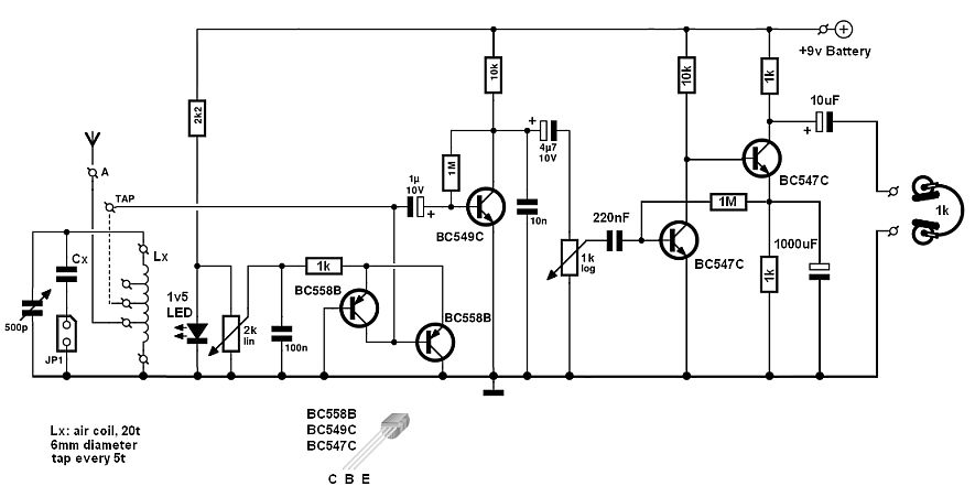
The RF circuit is composed of a two-stage tuned amplifier, using the BC558B transistors. It is followed by the BC549C detector and a powerfull audio amplifier that uses two BC547C transistors. It provides about 70-75dB of gain, which is necessary to drive a pair of 1k headphones. The volume on the headphones is much more than is needed and this ensures that no signal will be missed. The LED is a 1.5v red LED, which indicates the on/off state of the receiver, but also helps to stabilize the regeneration voltage of the amplifier, through the 2k potentiometer. For easier tuning you may use a multi-turn variable trimmer. You could also use a multi-turn variable potentiometer, but these cost many times the cost of the whole receiver. The variable capacitor can be taken out from an old radio. In the prototype I used a 360pF variable. Cx is optional and it can be switched on/off using the jumper, in order to extend the range of the receiver. The value of Cx is not critical and needs to meet your specifications. The only thing to take care is that this has to be a good quality capacitor, like a silver-mica, styroflex of NP0, in order to avoid frequency drifting.
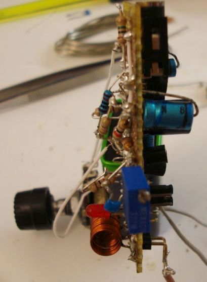
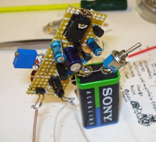
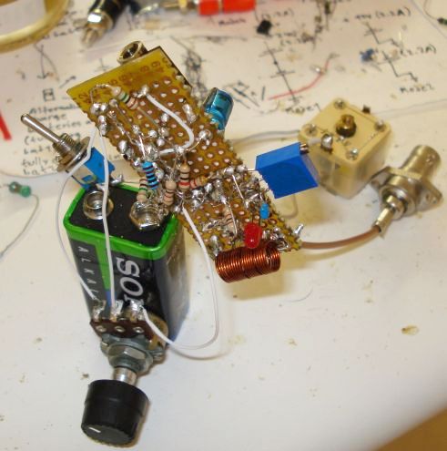
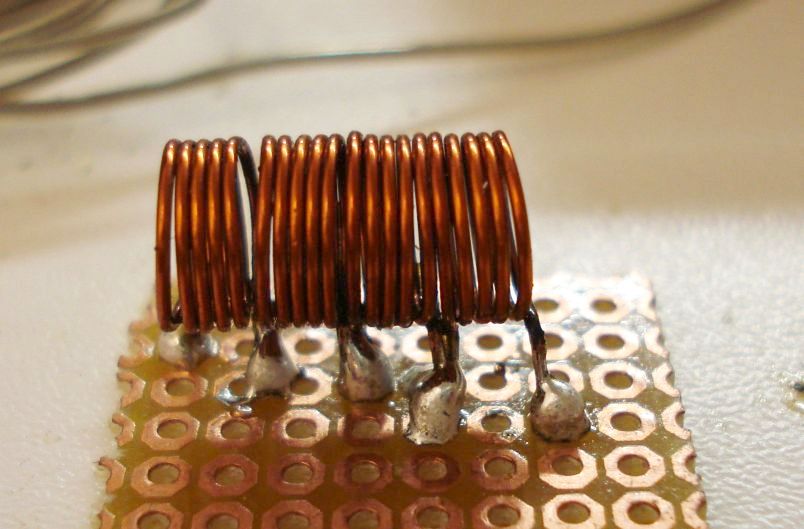
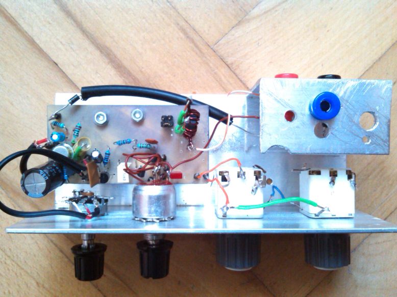
The prototype has been constructed on a small piece of proto-board and it is shown in the next pictures. Even with a so rude construction, the receiver worked at once.
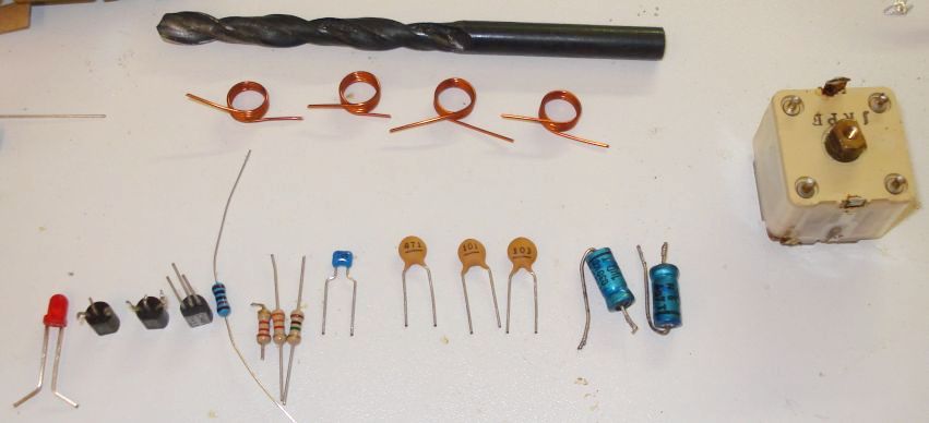
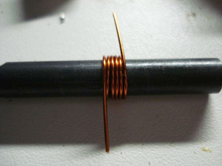
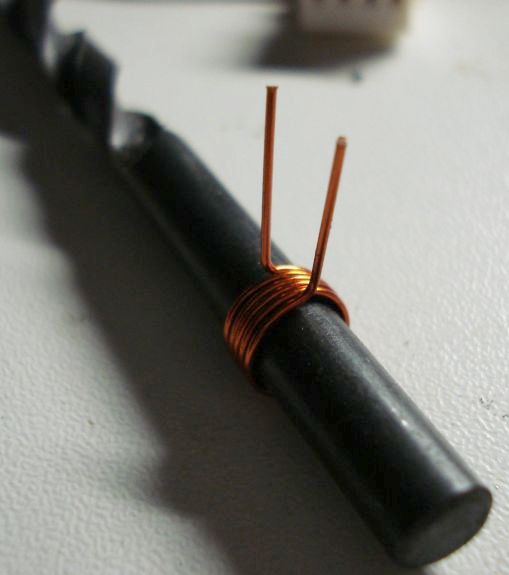
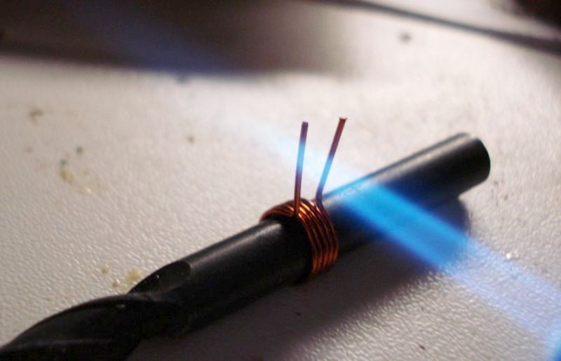
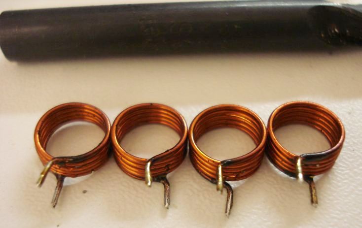
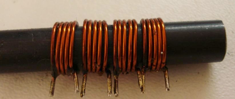
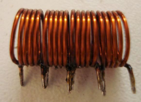
As I mentioned earlier, the most critical part is the coil. Therefore I provide you with details of how to wint it. Instead of winding a difficult single multi-tapped coil, my way is to wind multiple ones and connect them together, to form the multi-tapped coil. This is much easier and there is not much chance to make it wrong.
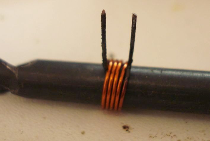
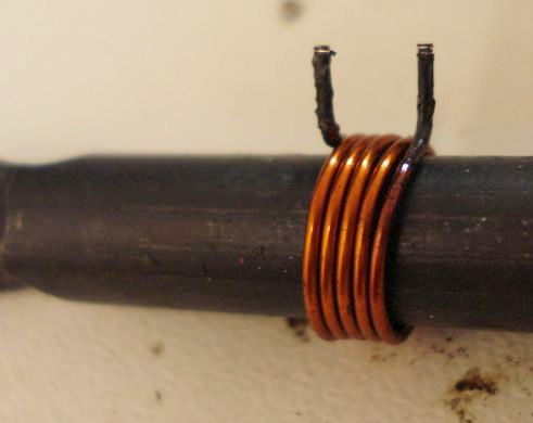
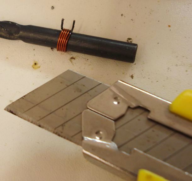
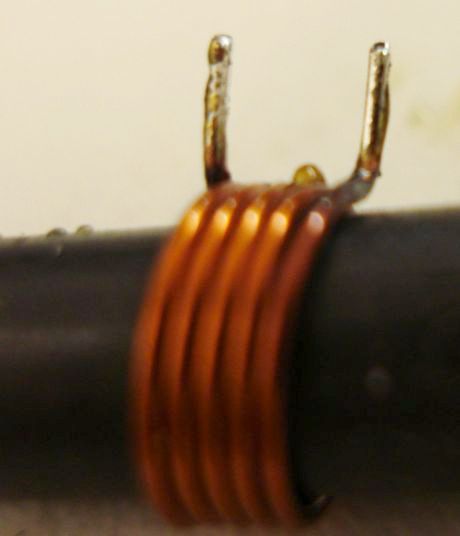
First, take a 6mm drill and wind 5 turns on it using 0.4mm or similar diameter wire.
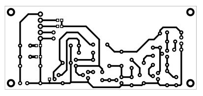
Here is a picture of a version built by Noro Mazik:
He says: "I used BC547 (beta 200) as a first stage in your amplifier and another transistor as the second one, with beta only 100.
I though that the gain was too much, especially for stations like CRI. I also experienced some motorboating when the volume was up
too much. On pcb I used 10 mm toroid coil with four times 3 turns, 2,3 uH. The pcb has an error and I had to add one hole for a
resistor in the amplifier. I also think it is a waste of cuprexit:) I used it as I was lazy to design my own so I was happy to
find it on your web."
Another circuit very similar to this one can be downloaded here. It uses an additional RF preamplifier, which seems to be better.