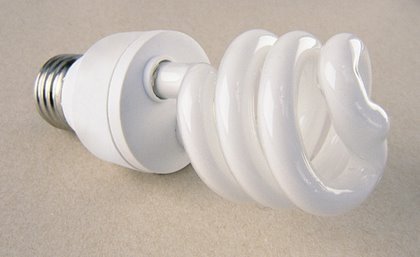
This electronic puzzle was a result of my changing a defective compact fluorescent lamp (CFL) in my kitchen. For some reason, I began to wonder if it would be possible to build a QRP CW transmitter using the electronic components salvaged from this derelict lamp.
Indeed, I'm pleased to report that a perfectly serviceable transmitter may be constructed! The only additional components required were the quartz crystal, and four of the five components needed for the output lowpass filter. The resulting transmitter produces up to 1.5 watts on 80m.
The photo below was snapped moments after completing my second QSO with the breadboard version of my prototype. A few minor changes were made since this picture was taken. The schematic (available at the top of this page) diagrams the most recent version.
My defective CFL was labled, "TriMax Electronic Fluorescent Lamp," Model #SKT320EAH,
20W, 120VAC, 60Hz. It was made in Korea by, or for, MaxLite. In order to gain access to the components I made a shallow, continuous, hacksaw kerf around the joint in the plastic base shown in the above photo of the lamp. One must be careful not to break the glass bulb; especially as these bulbs contain a small amount of toxic Mercury!
As soon as I had freed the circuit board, I checked for signs of component overheating. Finding no unusual discoloration, I set about unsoldering and cataloging the components. Here is a list of the components salvaged from my lamp. Of course, the exact type and value of the components you find will depend upon the make of your lamp. This web page shows some typical CFL schematics and part values.
I spent most of a pleasant day piecing together this little puzzle. The BUL128B transistors are aptly named, as these little "bulls" barely break a sweat hitched to this rig. The measured (Class-C) PA efficiency is approximately 50%. There's no need for a heat sink, and with a Vceo of 400V, they'll shrug-off any mismatch-induced collector voltage rise this circuit is capable of delivering.
T1 began life as a radial-leaded, ferrite-cored inductor. Through trial and error I found that a 7 turn secondary winding steps-down the impedance to roughly 15 Ohms. This provides a reasonable match to the base of Q2. T1 is the black cylinder just to the right of Q1 in the above photograph. Please "click-on" any of the photographs on this page in order to enlarge them.
T2 is a ferrite, toroid-cored conventional transformer. I rewound it as a 4:1 impedance step-down transformer. T2 is mostly hidden behind Q2 in the above photograph.
The output power varies with the activity of the quartz crystal used. My motley collection of crystals produce outputs ranging from approximately 1.0 to 1.5 watts with a 24Vdc supply.
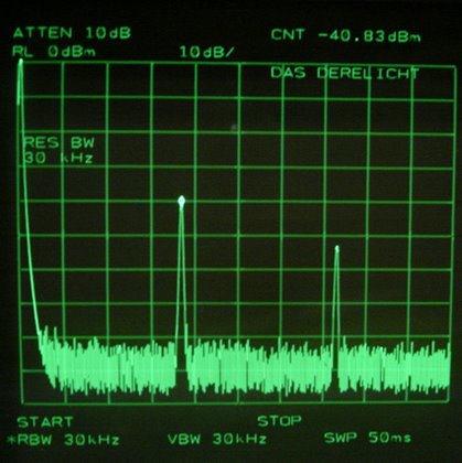
As indicated below, the second harmonic output signal amplitude is -40.8dB below the fundamental, and the third harmonic is down by at least 52dB. This measurement was made whilst the transmitter was delivering 1 watt into 50 Ohms via a 30dB pad.
Here is a short audio clip of Das DereLicht as received near Syracuse, NY (a distance of 268km), on N2JEU's web controlled receiver.
Transmitter Log
Date Station QTH His Mine Comments
12/12/08 WAØRAD Wentworth, MO 559 449 First QSO, 1950km path
12/12/08 N3RIK Perkasie, PA 579 559 30min ragchew, 10w to random wire
12/15/08 W3DWI Chamburg, PA 589 589
12/15/08 N2ESE Stanhope, NJ 589 579 40min QSO
12/16/08 N1RWW Taunton, MA 579 569
12/16/08 KN2CZZ Syracuse, NY 599 599 35min, Bill was running 10w to a dipole
12/16/08 K1PUB Boxboro, MA 599 589 35min ragchew
12/17/08 WA3MKC Pasadena, MD 579 579 Heathkit SB102, 100w to a vertical
12/17/08 W3DG Baltimore, MD 569 449 35min; Norcal 2030 (w/mod), 3w to a loop
12/18/08 N1LU Tuftonboro, NH 599 599+20dB 45min; 5w to a doublet
12/18/08 K4OSO Rockville, VA 589 569 90w to a G5RV
12/19/08 N8UM Oakridge, TN 589 569/579 1300km path, 200w to a vertical
12/19/08 VE2DWA near Ottawa 599 559 100w to a dipole

