Articles and information about the phasitron FM modulation tube.
Proceedings of the I.R.E. and Waves and Electrons
January 1947
A New System of Frequency Modulation
ROBERT ADLER, ASSOCIATE, I.R.E.
Zenith Radio Corporation, Chicago, Illinois.
Decimal classification: R148.2XR339. Original manuscript received by the Institute, February 4, 1946; revised manuscript received,-August 14, 1946. Presented, Winter Technical Meeting, New York, N. Y., January 24, 1946.
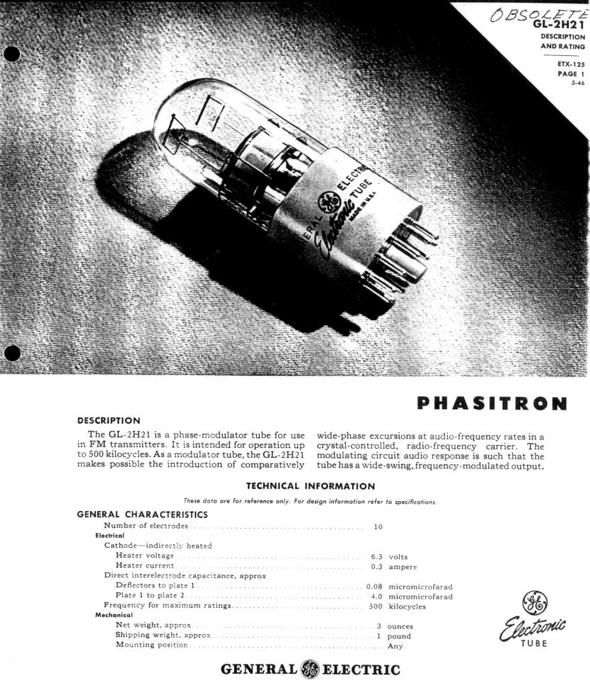
Summary - The development of a new phase-modulator tube is described. In a concentric structure of conventional dimensions, a radial electron stream is shaped into a wave-like pattern which progresses continuously around the cathode. Phase shift, 12 to 16 times larger than in conventional modulators, is produced by electro-magnetic deflection.The failings of early models are analyzed and the steps are reviewed which resulted in the development of a satisfactory tube structure.
THE PHASITRON system of frequency modulation, which has recently come into practical use, is based on a new tube structure. It is the object of this paper to review the development of this structure from its initial concept to the point where all technical requirements for hi-h-fidelity broadcasting as well as for communication transmitters were met by laboratory models. The step from the laboratory model to the production model and the design of complete high-fidelity transmitters incorporating the new modulator have already been described in the literature.[1]
Two different types of frequency-modulation transmitters have heretofore been widely used, based on reactance modulators and phase modulators. In transmitters using a reactance modulator, devices are required for continuous automatic correction of the aver age carrier frequency with respect to a crystal oscillator The frequency actually transmitted is then a function of the correction-system parameters and is not solely dependent on the crystal oscillator. Transmitters employing conventional phase modulators use a total frequency multiplication of several thousand times to obtain full rated deviation at the lowest audio frequencies. This high factor of multiplication requires two separate multiplier chains with frequency conversion between them, involving large numbers of tubes and circuits which present a number of problems with respect to random noise and spurious beat notes.
While none of these difficulties could be regarded as insurmountable, it appeared that crystal-controlled frequency-modulation transmitters could be simplified and perhaps improved in some respects if a phase modulator were known which would produce phase excursions far in excess of those obtainable with conventional modulators.
This thought stood at the beginning of the development. Analysis of an idea by C. W. Carnahan, who had proposed a mechanical phase modulator, indicated that inertia forces would make such a device impractical if not impossible; it appeared that only a vacuum tube could do the job. To operate efficiently in connection with conventional circuits and loads, such a tube would have to work with anode voltages and currents comparable to common receiver tubes. It seemed that this could be most easily accomplished if the usual concentric arrangement of anode and cathode were retained.
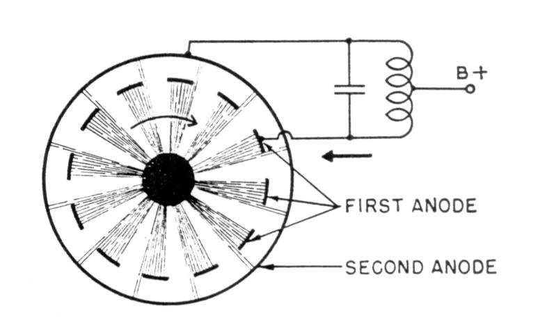
Fig. 1-Original concept of the phasitron modulator: a rotating bundle of electron beams.
With these rather broad directions in mind, let us now study the fundamental concept of the new phase modulator.
Let us assume that by some device in the black central portion of Fig. 1 the electrons which fly radially, away from the cathode are split into discrete radial beams-twelve are shown in this figure - and that the first anode consists of twelve bars, all connected. Let us further assume that the device in the center rotates, with uniform speed, so that the electron beams alternately hit the twelve bars which constitute the first anode,
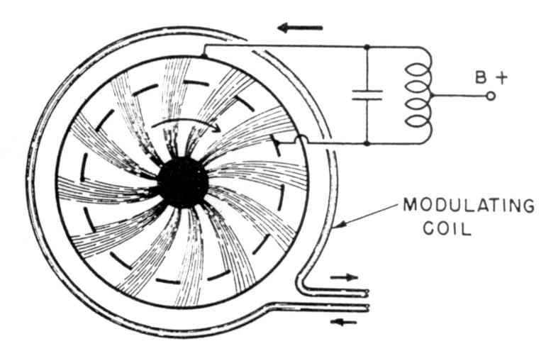
Fig. 2-Phase advanced 180 degrees by axial magnetic field.
or pass between them to strike the second anode which is a full cylinder. The tuned circuit connected from plate to plate is then excited at a constant frequency which depends on the speed of rotation of the device in the center.
Now let us apply a magnet field parallel to the cylinder axis. We can produce it by a concentric coil wound around the tube, as shown in Fig. 2. All electron beams are now deflected clockwise and thus advanced in the direction of rotation, so that they strike all plate bars ahead of schedule. In Fig. 2 the deflection has been made equal to the width of one bar, so that the plate currents which drive the push-pull circuit are advanced in phase by 180 degrees. If the magnet field were reversed the deflection would be counterclockwise and would retard the arrival of the beams at the anodes. The amount of phase shift obtained for a given plate voltage depends only on the magnetic field intensity.
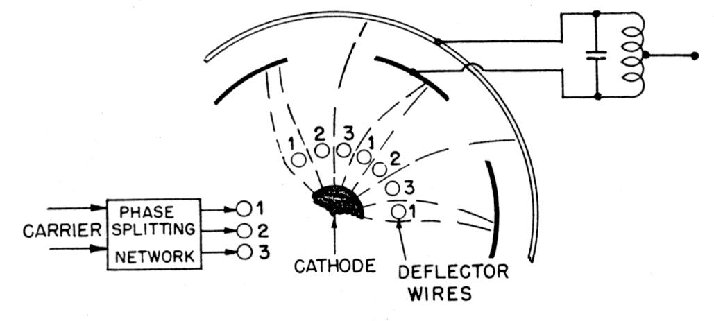
Fig. 3-Generation of rotating electron beams by a deflector structure carrying three-phase potentials.
Let us now turn to the device in the center which generates the rotating beams. Fig. 3 shows schematically a sector of the first tube structure actually built. A cylindrical cathode is surrounded by a number of parallel wires of smaller diameter, arranged on a cylindrical surface around it. These wires are consecutively numbered 1, 2, 3, 1, 2, 3, etc.; all "1's" are interconnected, as are all 2's and 3's. The three groups are fed from a three-phase network which is driven by a crystal oscillator. Fig. 3 shows conditions at an instant when I is on its positive peak while 2 and 3 are negative; the electrons passing around rods labeled "1" are focused together and deflected away from rods 2 and 3. Most of the current, therefore, flows to the first anode. One third of a cycle later, rods 2 will be at their positive peak while 3 and 1 will be negative, and the regions
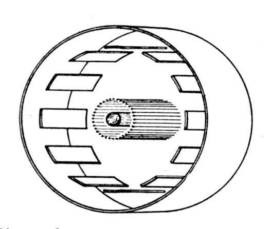
Fig. 4-Electrode structure of first operating model.
where most electrons strike will have traveled clockwise by a corresponding angle; so, as the potentials travel clockwise from wire to wire, we obtain the equivalent of a rotating system of beams.
The rotating structure of electrostatic fields which produces the electron beams might well be compared to, the rotating magnetic field generated by the stator of a slow-running three-phase motor. Such a stator has 3 N poles, N being the number of cycles for one complete revolution of the magnetic field.
Fig. 4 shows, schematically, the first tube actually built. Its first anode had 12 bars, and the three-phase deflector correspondingly consisted of three groups of 12 wires each, or 36 in all. They were operated at a low positive potential with the three-phase excitation superimposed. Fig. 5 shows the first model, with the three-phase connections led out at the top.
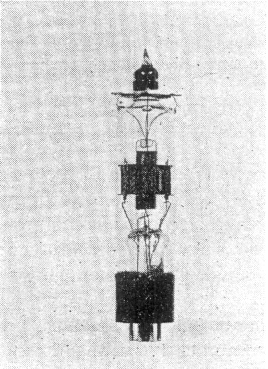
Fig. 5-First operating model: connections to three-phase deflector elements appear on top.
The tube was first tried out with a carrier frequency of 60 cycles. The push-pull output circuit was connected through a transformer to the oscilloscope and the sweep synchronized from one terminal of the three-phase input. A coil was arranged around the tube to produce the axial magnet field; it was fed from a variable direct current supply so that the phase shift could be accurately plotted as a function of current through the coil. Plus and minus 720 degrees-or plus and minus two complete cycles-were obtained with this first tube.
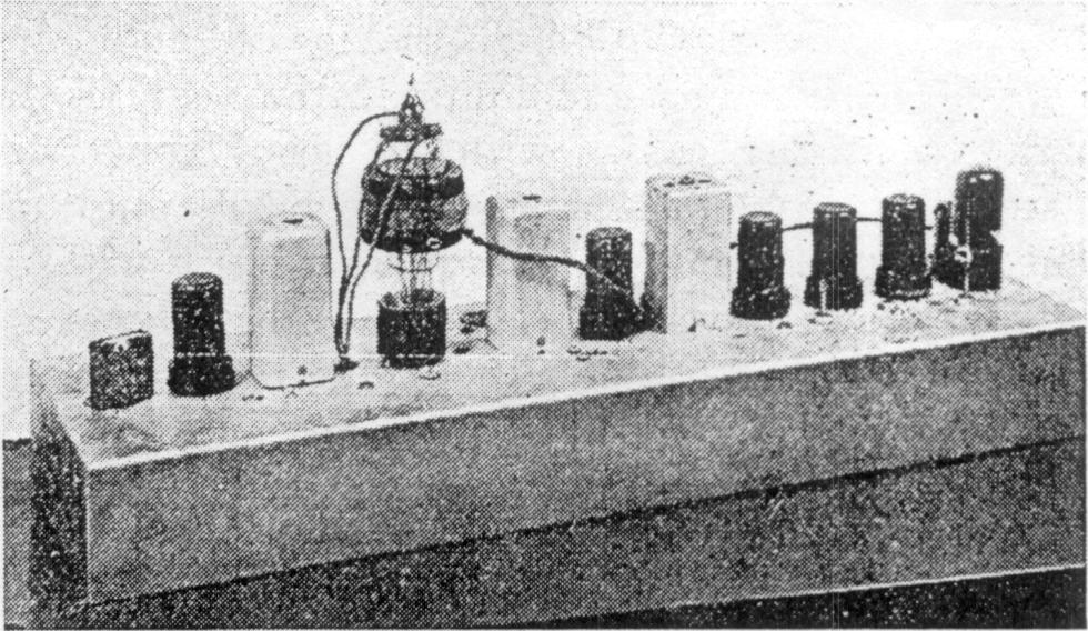
Fig. 6-Frequency-modulation broadcast transmitter, showing (left to right): 235-kilocycle crystal, oscillator tube, three-phase network, modulator tube with audio deflection coil, push-pull output transformer, first doubler, frequency multipliers to 45.1 megacycles.
Next, a complete frequency-modulation transmitter was built (see Fig. 6), which consisted of a crystal oscillator on 235 kilocycles, a simple phase-splitting network, the modulator tube, and a string of multipliers to reach the final frequency of 45.1 megacycles. The total multiplication was only 192 times.
Using the full 720 degrees phase excursion, this transmitter was capable of 75 kilocycles deviation at an audio frequency of 30 cycles. A similar unit, using the same multiplication, was built to operate as exciter for Zenith's 50,000-watt station, WWZR, and several successful test transmissions were made over this station.
Only a fraction of one watt of audio power was needed for the modulating coil. The inductance of this coil is instrumental in obtaining constant frequency deviation over the entire audio band; with a constant voltage applied to the coil, this inductance tends to make the current, and consequently the phase shift, inversely proportional to the frequency of the audio signal. This is exactly the characteristic required to obtain constant deviation.
The first model of the new modulator tube had several failings. Most apparent was the low signal output: with one milliampere direct current on each anode,
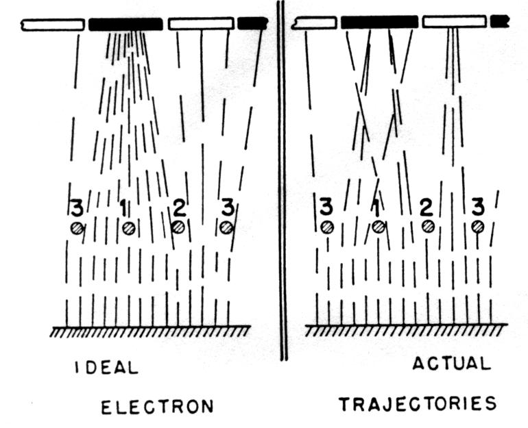
Fig. 7-Comparison of desirable electron trajectories with those probably produced in first model.
only about fifty microamperes of signal current was obtained. This low current efficiency caused a considerable amount of hiss; the noise level was 58 decibels below full deviation, instead of 70 or more.
The low current efficiency-in this first tube was probably caused by the fact that the action of its three phase deflector electrode was far from ideal, even in theory. This is illustrated in Fig. 7. The left half of this figure shows the electron trajectories in that form which would have been most desirable. The right half of the figure gives a greatly simplified and schematized idea of the actual trajectories. The strong aberrations which occurred close to the deflector wires nearly destroyed the desired focusing action and reduced the current efficiency considerably.
The same strong fields close to the deflector wires which produced defocusing also gave rise to a second undesirable effect: when a gradually increasing magnetic field was applied to the tube, the phase shift did not rise strictly in proportion but showed irregular deviations from the desired linear relation. Correspondingly, a small incremental field produced varying amounts of phase shift at different points of the field-versus-phase characteristic. At low audio frequencies where large phase excursions are required considerable distortion was caused by these irregularities.
The observed type of distortion can be explained if the tangential velocity of the electron beams is assumed to vary from point to point along the periphery of the first anode; for the electrical phase shift produced by a small incremental field is proportional to the time interval in which the beams, through their rotary motion, could cover a portion of the periphery equal to that over which they are deflected by the incremental field. Because it makes no difference which part of a given anode bar an electron strikes, the peripheral velocity matters only in the regions of current transition-at the 24 edges of the 12 first-anode bars.
If we assume an irregular distribution of tangential velocities around the periphery, the average of the velocities measured at the 24 edges may well be different from the average taken over the whole periphery; then, if we rotate the entire system of velocities by applying
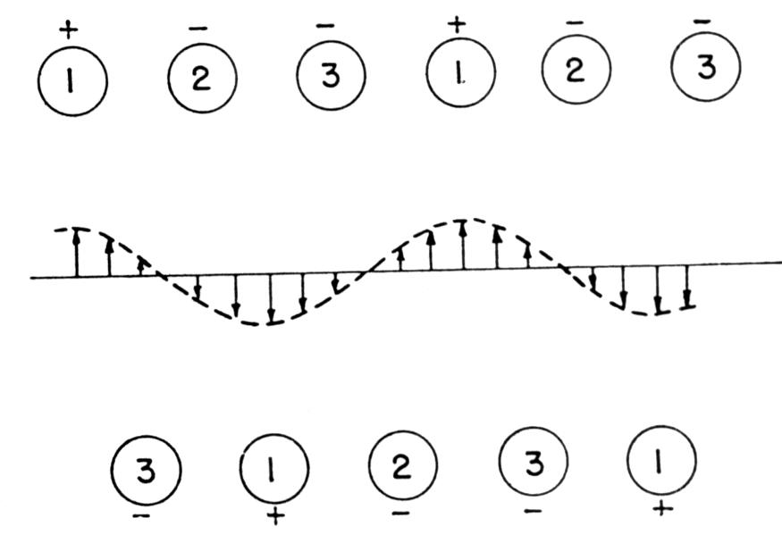
Fig. 8-Schematic view of transverse deflector arrangement.
an axial magnetic field, those velocities appearing at the 24 edges-and consequently their average-are bound to vary. In a position where this average is high, a larger incremental field is required to produce a given increment of phase.
There can be little-doubt regarding the existence of an irregular distribution of tangential velocities in the tube structure described. Cyclic variations (one cycle for each deflector wire) were bound to be present, and because there were 1'2 wires for every edge, all even harmonics of such cyclic variations would appear in phase on all edges. More detailed study of the distortion effect tended to verify the above analysis. In the following we shall refer to this effect as "structural distortion."
Two more tubes were built which differed from the first only in detail. Their performance was quite similar.
If the new, phase modulator was to meet practical requirements it seemed that the signal output would have to be at least five times higher for the same direct current on the plates, and the structural distortion would have to be substantially suppressed. An entirely different deflector system was needed which would produce a smoothly rotating electrostatic field without noticeable speed variations from point to point.
Fig. 8 illustrates the principle of a new deflector system designed to produce such a field. Two rows of short parallel wires face each other across a center plane. Each row consists of three groups which are interlaced and connected to a three-phase supply as before. The direction in which the voltages travel is the same in both rows, but the wires "I" in one row face the middle between the wires "2" and '3" in the other. A transverse electric field (vertical in Fig. 8) is produced in the center plane between the two rows, and if we plot this field at a given instant from left to right along the center plane we find that it varies quite smoothly, very much like a sine function. Because the individual deflector wires are not in the immediate vicinity of the center plane, their strong local fields can no longer upset the smooth character of the field distribution.
To save time-consuming computation of the field along the center plane, an electrolytic model was built as shown in Fig. 9. On each of two bakelite bars, three bare wires were wound interlaced.
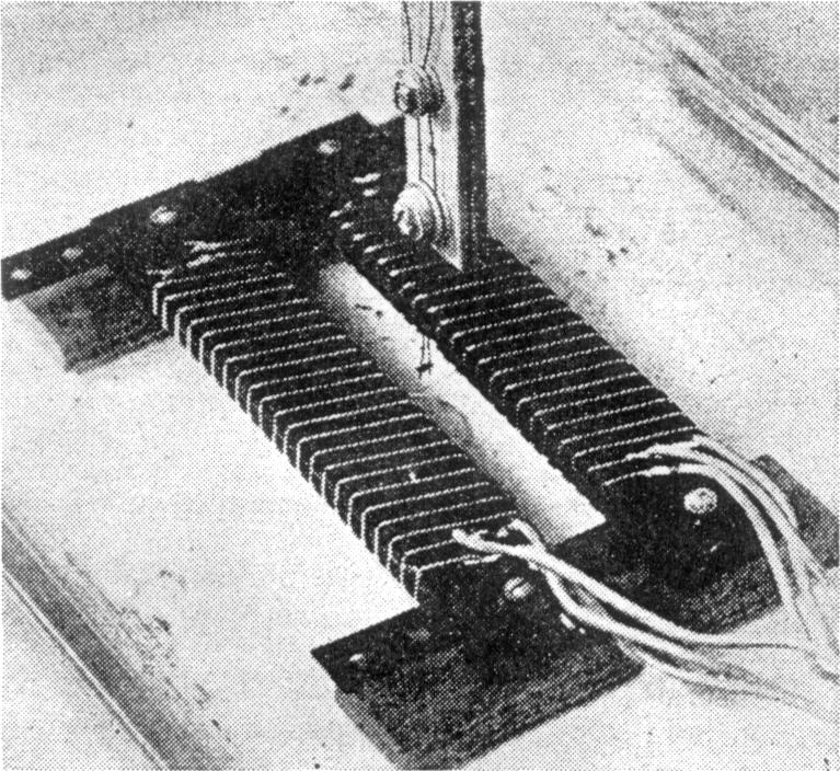
Fig. 9-Electrolytic model for the study of transverse deflectors.
Three stationary voltages, corresponding to an instantaneous condition of a three-phase system, were applied to the wires on each bar. The short portions of these wires which faced each other across the gap represented the deflector elements shown schematically in Fig. 8. A two-element probe was moved along the gap between the bars by means of a lead screw. The two elements were positioned symmetrically on a line perpendicular to the center plane, and the potential of each element was plotted with reference to the three-phase neutral. Fig. 10 shows one of these plots, which not only proved that a field distribution closely approaching a sine function could be produced but also yielded data on the intensity of the transverse field as a function of configuration.
To utilize a deflection system of this new kind in a concentric tube structure, the two parallel rows of short wires had to be bent so as to form two parallel coaxial circles, and the electron flow had to be so arranged that all electrons would travel radially and pass near the center plane between the two deflectors.@ This led to the concept illustrated in Fig. 1 1. The electrons are shown here in the shape of a sharp-edged disk from which one quarter has been cut away so that the lower deflector becomes partly visible. The electrons fly along radial lines until they pass between the two deflectors; here they are deflected upward or downward according to the wave-shaped transverse field; and as this field travels around the cathode, so do the waves in the electron disk.
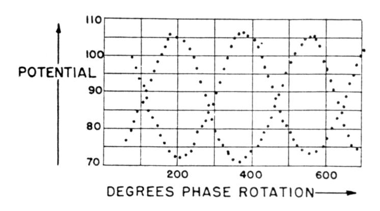
Fig. 10-Potential plot obtained with the electrolytic model shown in Fig. 9.
It is essential for the proper function of this deflector system that most electrons pass near the center plane and that the deflector wires with their strong local fields remain substantially outside the disk-shaped electron stream.
The black and white fields marked A and B represent portions of the first and second anode, respectively. The white fields correspond to windows in the first anode, and in the position shown in Fig. 11 there is one window visible above each valley in the electron
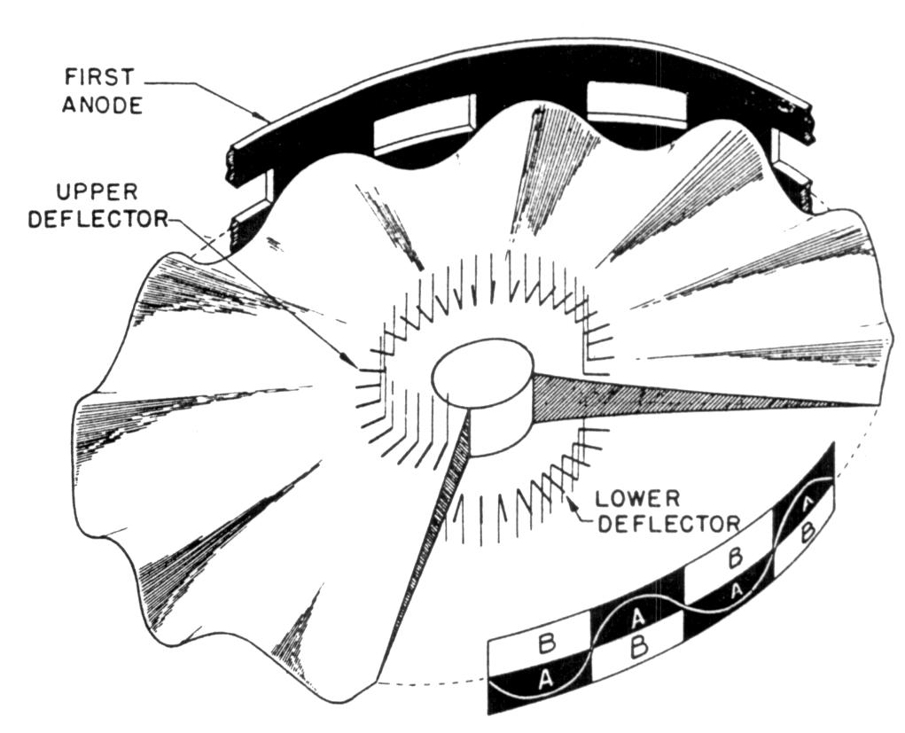
Fig. 11-Transverse deflection produced in a disk formed by electrons traveling radially.
disk, and another window hidden below each peak. As shown more clearly in the schematic sector on the lower right of the figure, the thin edge of the ruffled disk strikes only full portions of the first anode at this moment, and no current flows through the windows to the second anode. If a modulating magnet field of proper size is applied at this instant, the picture changes as shown in Fig. 12; all current now flows to the second anode and the phase is advanced 180 degrees.
So far, the last two figures merely represent a mental concept. To make the electrons actually travel along such trajectories that they pass near the center plane and come to a line focus on the periphery,
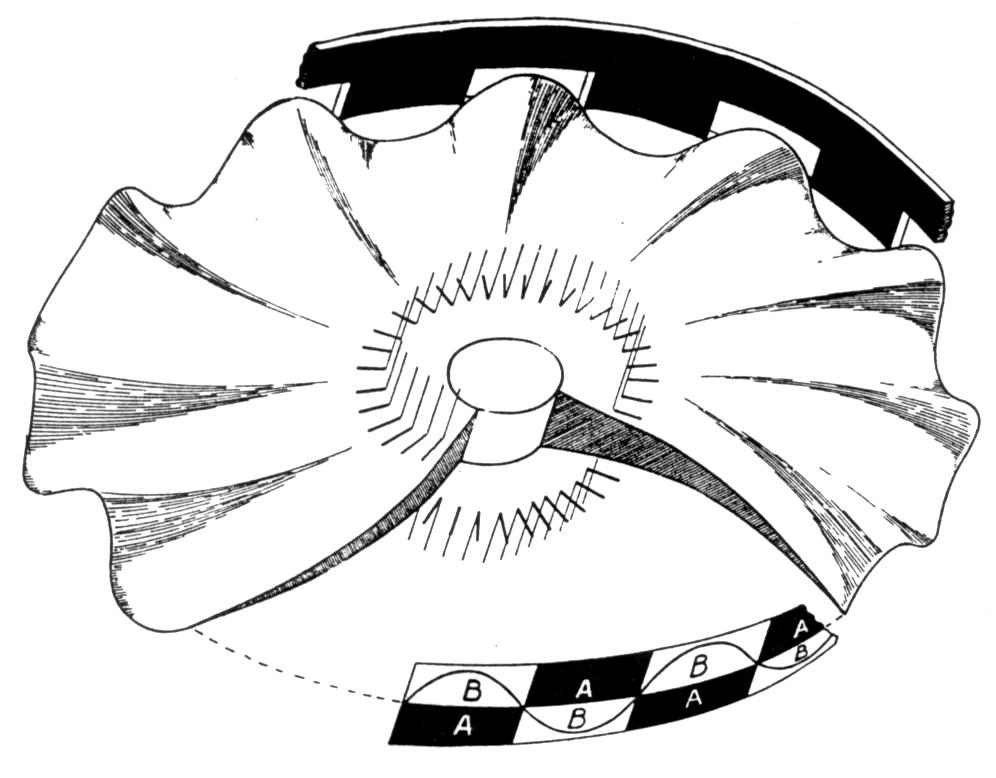
Fig. 12-Electron-beam configuration in the presence of an axial magnet field.
we must add an electron-optical system. The problem is not too difficult because accurate focusing as in a cathode-ray tube is not needed. Fundamentally, we need an electron gun developed into a full circle. Again, the electrolytic model method was used to arrive at a useful arrangement. Because only radial and axial fields exist in a concentric structure, a thin wedge-shaped sector will suffice for a model. This has been well-known for some time. [2]
Fig. 13 shows the potential distribution plotted with such a wedge model.
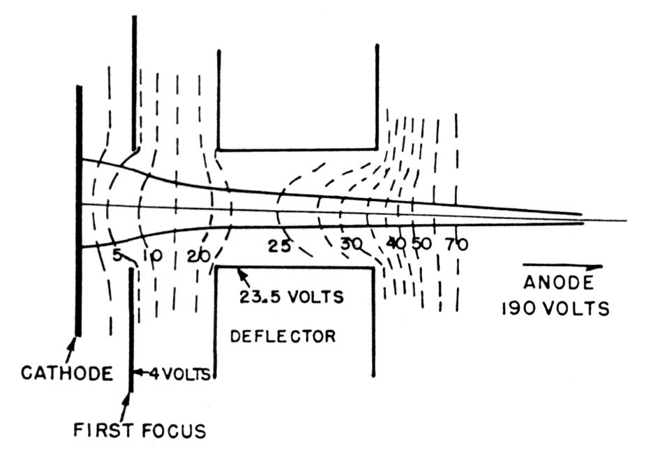
Fig. 13-Potential plot obtained with electrolytic wedge model of.a tube structure intended to produce the configuration shown in Fig. 11.
The deflectors are here regarded as solid surfaces. The anode (not visible in this figure) would be somewhat farther to the right. Two electron trajectories are drawn in to show that they have the desired character; their shape was found by geometrical construction. A number of such plots were made, varying the ratio of potentials on first focus, deflector electrodes, and anode. It was found that the deflectors had to be longer in the direction of electron travel than had been anticipated; but instead of making the little wires longer, a solid ring was laid around each deflector electrode and the two rings brought out to a separate contact.
Fig. 14 shows the tube layout which resulted from these plots. Around the cathode there are two cylinders -the first focusing electrode.
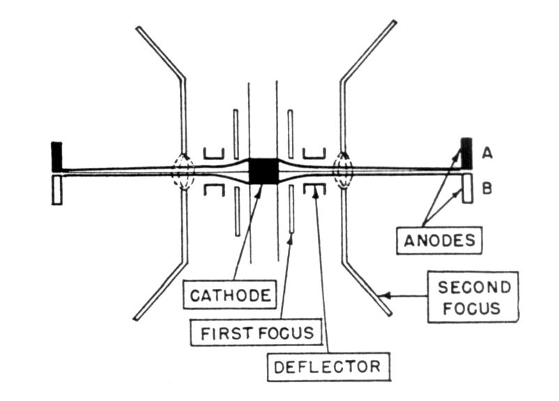
Fig. 14-Section of improved tube structure. Modulating flux is concentrated between edges of second focusing electrodes.
Next come the two deflectors which carry the short radial wires; they are surrounded by the two rings just mentioned, called the second focusing electrode. These rings are made of soft iron and continued outside the supporting micas by more soft iron; they help to concentrate the modulating magnet field into a narrow region, as indicated by the dotted lines. Finally, the anodes A and B terminate the concentric structure.
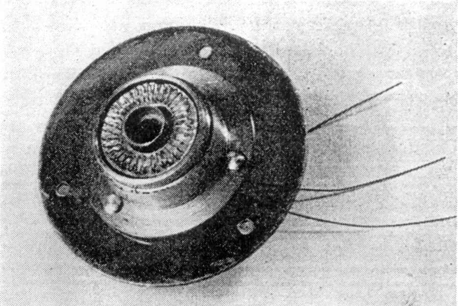
Fig. 15-Three-phase deflector electrode, mounted together with first and second focusing electrodes. Two such assemblies faced each other in the completed tube.
Fig. 15 shows one of the deflectors with the 36 short radial wires and the first and second focusing electrodes mounted on one mica.
In the first tube of this new kind, the checkerboard pattern of anode fields A and B was made up of 24 rectangular metal fins, 12 to each anode, all lying in one cylindrical plane and properly interconnected.
Results with the new model were most encouraging. With careful adjustment of the focusing potentials the structural distortion could be almost entirely eliminated; current efficiency was improved by a factor of three or four, and the hiss level was reduced by a much larger factor, probably because the electron stream was no longer intercepted by a positive grid. With a total multiplication of 192 times, the hiss was now more than 70 decibels below full deviation.
The new modulator operated with very low distortion down to about 100 cycles. But at the very large phase excursions required for 50 cycles at this low multiplication, nonlinear distortion appeared. It was mostly of the third-harmonic type, quite similar to that which conventional phase modulators produce when they are used over too wide an angle. Fig. 16 shows the geometrical reasons for this type of distortion; for large deflections, the arc which the electron trajectories cover on the periphery of the tube increases faster than the angle of deflection, so that the graph of phase shift versus magnet field becomes steeper in the regions of large phase shift.
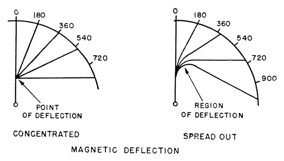
Fig. 16-Nonlinearity at large phase excursions. Distortion is reduced by concentrating the region where deflection occurs.
The figure also shows that it is better to concentrate the 'magnet field close to the center, rather than spread it out over the whole tube. It was for this reason that the second focusing electrodes were made of soft iron.
To suppress the nonlinearity just explained, a number of methods were open. The most straightforward solution would consist in introducing a controlled amount of saturation into the magnetic path so that strong fields would be reduced by just the right amount. Another solution consists in driving the deflection coil from a pair of pentodes in push -pull, so adjusted that their combined transconductance is peaked at the operating point. With a modulator built according to this idea, total distortion at 50 cycles and full deviation could be reduced to 1.35 per cent with a multiplication of only 192 times. The corresponding phase excursion was plus and minus 430 degrees.
In the further course of the development, the hiss level was reduced to such an extent that, at the present time, it is considered more convenient to double the multiplication and dispense entirely with any artificial means of linearization.
A few words about the circuits used to produce the three-phase excitation might be in order at this point. Originally, the simple resistance-capacitance network on the right in Fig. 17 had been used in all experiments.
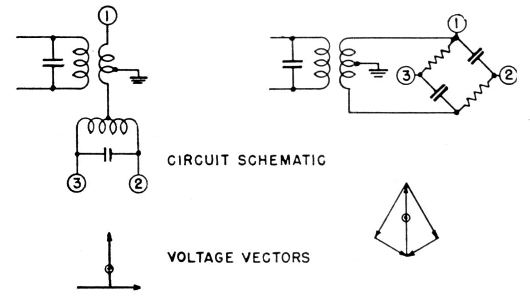
Fig. 17-Networks for generating three-phase potentials.
Later it was found that good wave form on the deflector electrodes was important for reducing distortion to a minimum, and the network on the left, derived from the well-known Scott circuit, was substituted.
The tube described above might have been used in frequency-modulation broadcast transmitters, but its output level was still inconveniently low, and certainly too low for use in communication transmitters. Checking into the causes for the low output, it was found that there existed a resistance of only, about 10,000 ohms between the two anodes, evidently as a consequence of secondary emission. Such secondary emission would reduce the radio-frequency component of the anode current, even without load, because the anode struck by more electrons would also emit more secondaries. In addition, only low-impedance load circuits could be used. In the first tube of the new kind the anode fields A and B were arranged side by side, and a direct-current voltage applied between them would only draw all current to the more positive anode. A different anode structure appeared necessary to suppress secondary emission effects.
A tube was then built with an anode structure as shown in Fig. 18. This, in effect, is a return to the original model in which holes in the first anode represented the active parts of the second; but this time, a helical suppressor was set between the two anodes.
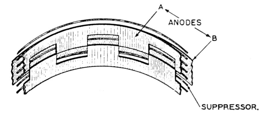
Fig. 18-Arrangement of first anode, suppressor, and second anode in last experimental model.
Fig. 19 shows an X-ray photograph of this last experimental model. The two deflectors with their little wires, the outer focusing rings with their magnetic extensions, the checkerboard fields of the first anode,
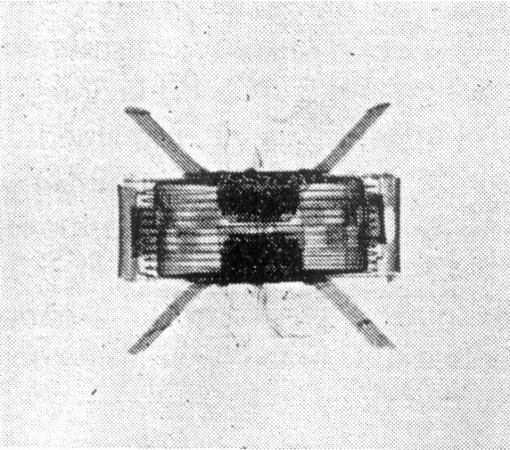
Fig. 19-X-ray view of last experimental model. Electrodes inside the suppressor helix may be identified by comparison with Fig. 14.
and finally the suppressor and the second anode appear in this picture. The current efficiency of this tube was several times that of the previous model; the signal component was equal to more than half the direct current on each plate. The output impedance was several megohms. The hiss level, with a multiplication of 192 times, could not be measured accurately; with twice that multiplication, it was found to be 78 decibels below full deviation.
The large output from this tube made it possible to use it in a communication transmitter (see Fig. 20). Here, a crystal oscillator was used to drive a three phase network at 8.37 megacycles. In the output from the phase-modulator tube, a high-inductance permeability-tuned load circuit delivered 30 volts into the grid of a 6AC7 tube operating as quadrupler.
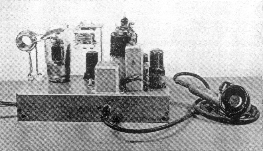
Fig. 20-33-megacycle communication transmitter using experimental phasitron tube.
More than sufficient power was available in the quadrupler output to drive an 815 dual beam tetrode at 33.5 megacycles. The whole transmitter had only four tubes.
At this point, it seemed that the project had grown beyond the purely experimental stage. Its further development was then taken over by F. M. Bailey and H. P. Thomas, of the General Electric Company.
ACKNOWLEDGMENT
The author wishes to thank E. C. Ewing, of the Zenith Radio Corporation, for his assistance in making the experimental tubes, and E. Phillips, of the Raytheon Manufacturing Co. (formerly of Zenith), whose initiative and co-operation contributed greatly to the success of this project.
[1] F. M. Bailey and H. P. Thomas, "Phasitron FM transmitter," Electronics, Vol, 19, pp. 108-112; October, 1946.
[2] M. Bowman-Manifold and F. H. Nicoll, 'Electrolytic-field- Plotting trough for circularly symmetric systems," Nature, vol. 140, p. 39, July, 1938.
maintained by
updated December 2004
New: A tour of Steve Hemphill�s Workshop!
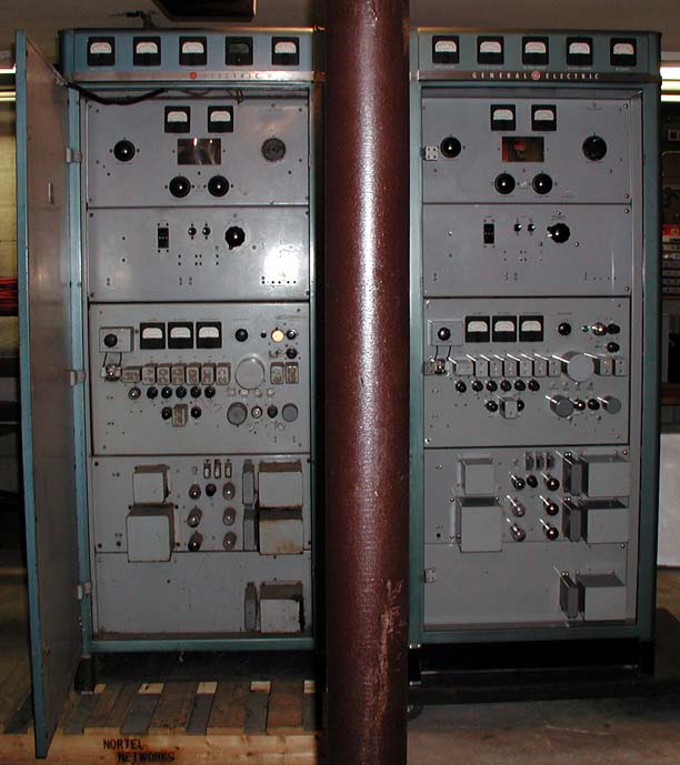
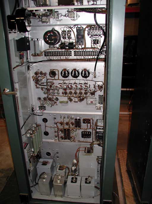
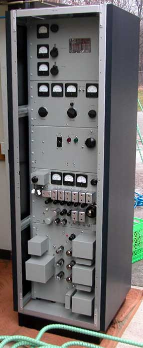
Steve sent me these pictures of his Phasitron transmitter restoration workshop back in the spring of 2003, and I have been derelict in my duty to get these posted. So with apologies to Steve, here are the photos that document his stunning work on restoration of not one, but two GE 250 watt Phasitron FM transmitters. This picture shows a "before" transmitter on the left, and an "after" transmitter on the right:
Here is the rear of the restored Phasitron transmitter. It looks brand new:
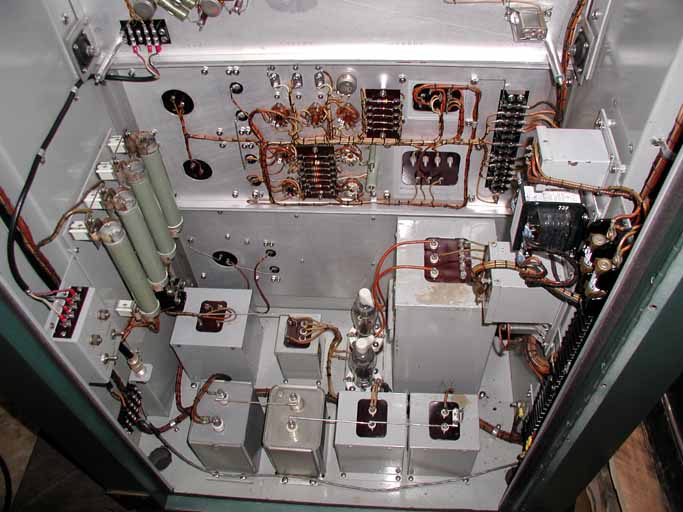
Here is a closeup view of the lower part of the transmitter � the power supply section, with all of the "heavy iron" components:
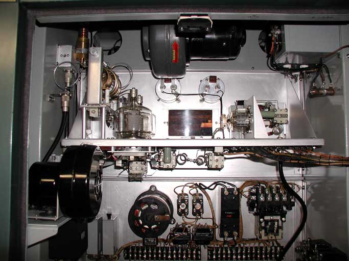
And finally, here�s a closeup of the 250 watt push-pull PA:
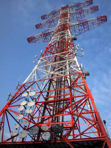
Steve Hemphill's Alpine Tower Project
Steve is working on a "re-enactment" of Major Armstrong's 44 MHz FM broadcasts from Alpine tower in New Jersey. Here's the Alpine tower:
And here is Major Armstrong's original transmitter building built in 1937 that housed the W2XMN station (the world's first FM broadcast station) - now the Alpine museum:

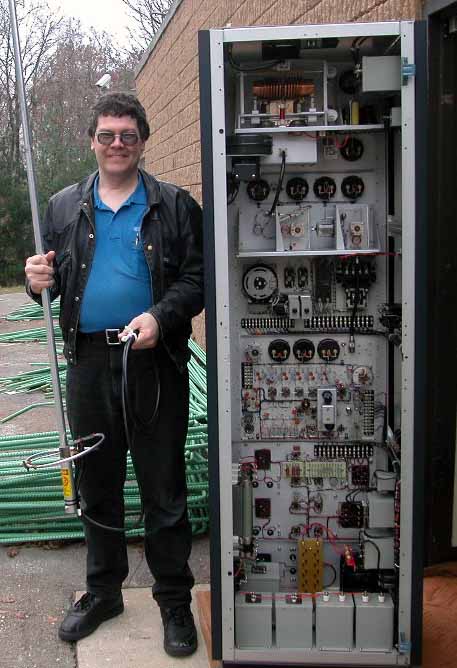
Steve has built a Phasitron FM transmitter operating at 44.1 MHz for this project. Although the Phasitron was not even invented yet when Armstrong began his broadcasts, the technology is approximately correct for the era. Here is Steve's 44.1 MHz transmitter, sitting just outside of the Alpine Tower equipment room:
Gorgeous work, Steve! Here is a view of the back side of the transmitter, and the front side of Steve, who is holding a Ringo Ranger antenna modified for use at 44.1 MHz. Hopefully, the transmitter was not operating when this picture was taken:
Steve says that the commemorative broadcasts will be done sometime in the spring or early summer of 2005. (I hope he will QSL!)
PHASITRON NEWS FLASH: Steve Hemphill builds reproduction of Phasitron exciter, shown at NAB2002!
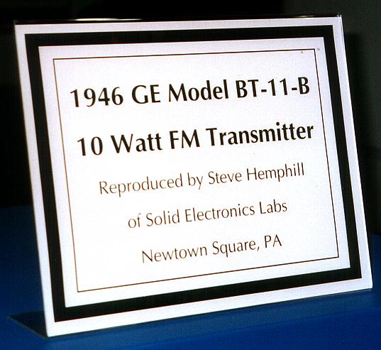
There was a special treat in store at NAB 2002, in the Belar booth. Steve Hemphill has built a working reproduction of a 1946 GE model BT-11-B 10 watt FM transmitter/Phasitron exciter! Here's a picture of it:
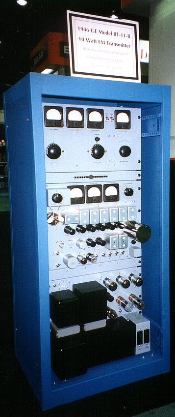
Steve's labor of love has produced a gorgeous Phasitron exciter, that looks like it just rolled off the GE assembly line over half a century ago! Steve built the exciter mainly using an original technical manual as the reference. Almost every detail is authentic - all the way down to the beautifully made shield covers for the frequency multiplier tuned circuits, and the mu-metal shield for the Phasitron tube itself. And, the exciter works! Arno Meyer told me, "It makes 1% distortion at 50 Hertz!" (In a phase modulator system, the greatest distortion comes at the lowest frequencies where the phase modulation is highest.)
And here's the rogues' gallery:
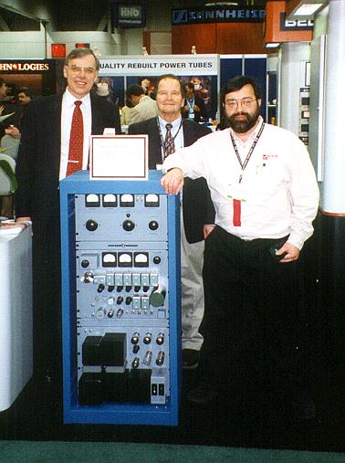
From left to right in this picture: Geoff Mendenhall, W8GNM (ex-W9NEZ), an engineering vice president at Harris Broadcast in Mason, Ohio; Arno Meyer, founder and president of Belar Electronics; and Dave Hershberger, W9GR (creator of this web page), principal engineer at Axcera.
Steve Hemphill used Arno Meyer's facilities at night to produce the Phasitron exciter reproduction.
Here's the sign that appears on top of the exciter:
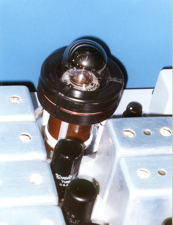
Here's the Phasitron tube (with the mu-metal cover removed) in its natural habitat - inside the modulator coil:
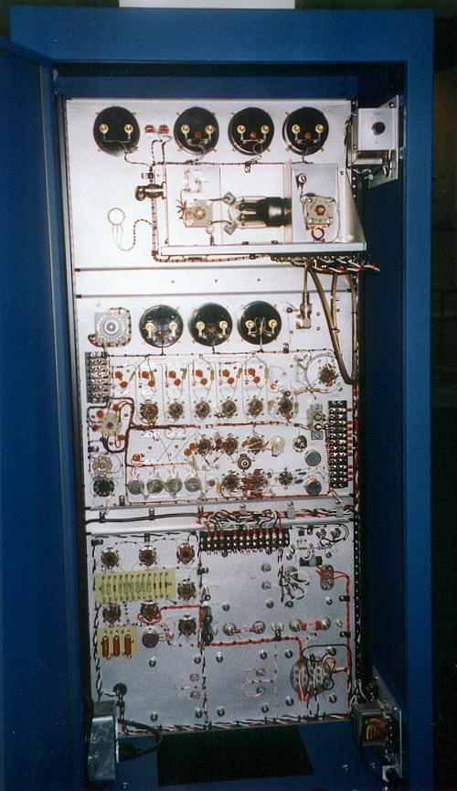
The back of Hemphill's exciter is beautiful:
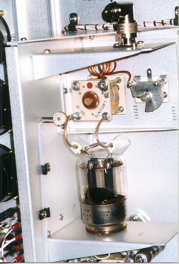
Here's a closeup of the 10 watt PA in the exciter:
Steve was unfortunately unable to attend NAB this year but he was pleased to hear that his handiwork attracted lots of attention.
I talked to Steve after NAB and we discussed the idea of running stereo composite through the Phasitron, and possibly even putting it on the air. Steve said that he widened out the bandwidth of the first multiplier or two to 100 kHz either side of carrier, and that he was able to get about 25 dB of stereo separation that way! And, he even passed a RBDS subcarrier through the Phasitron! But alas, widening out the bandwidth produced unwanted harmonic multiplier sidebands on either side of the output signal, which exceeded FCC rules. Steve had to narrow the bandwidth of the multipliers back to the original 30 kHz to meet occupied bandwidth rules.
But I suggested that Steve might be able to equalize the stereo composite with a two-section baseband equalizer (rising at 12 dB/octave) to overcome the (doubly tuned) first multiplier's narrow bandwidth, and get decent stereo separation.
Now that would be a first - stereo from a Phasitron tube! (UPDATE: see link to Steve's e-mails below - he did it! The Phasitron has gone stereo!)
Bill Gillman suggested breaking the multiplier chain partway up, and inserting a second Phasitron tube to inject the L-R modulation.
Radio World conferred upon Steve an honorary "Cool Stuff" award for his Phasitron exciter. "Cool Stuff" awards are normally given to new products. But even though the Phasitron exciter is 56 years old, it was still too "cool" to pass up by the awards committee at Radio World.

Radio World's 2002 Cool Stuff Here's the link to Radio World's 2002 "Cool Stuff" awards.
E-mail from Steve Hemphill to Paul McLane and the Phasitron goes STEREO - Steve Hemphill himself provides background information and details on the construction of his Phasitron exciter - and he reports on the successful development of a composite baseband equalizer, allowing FM STEREO to come out of a Phasitron!
Question: which station had a Phasitron FM exciter on the air, in regular service, at the latest date?
I would like to know how
long Phasitron rigs were on the air. Some people who have sent me
e-mails talk about various FM stations that had Phasitrons on the air
until about 1970, or the early 1970s at the latest. But I think my
first college's FM station has that beat. WGCS 91.1 FM
in Goshen, Indiana had a Phasitron equipped GE 250 watt FM transmitter
in regular service until the fall of 1979. In fact, it was their only
transmitter. Of course, if you had a Phasitron rig, you were on the air
in mono. To go on the air in stereo, WGCS replaced their old 250 watt
GE with a 5 kilowatt Gates FM-5H with a TE-3 exciter. (They raised
power at the same time, obviously.) If anybody knows of an FM station
that had a Phasitron rig on the air in regular service later than 1979, please let me know. E-mail me here: Click to email me. To qualify, the Phasitron rig must have been the main transmitter in regular use, not a backup. Other Phasitron news - two versions of the tube: Some e-mails I have received recently have informed me that there were two
different kinds of Phasitron tubes made by GE. Two different tube
historians have written to me about the 2H21 and 5593 incarnations of
the Phasitron. One of the tube historians wrote to me: As a tube-history enthusiast, I've
tried hard to figure out any real difference between the 2H21 and 5593
from the GE data sheets. (The 2H21 is rated to 500 kHz; the 5593
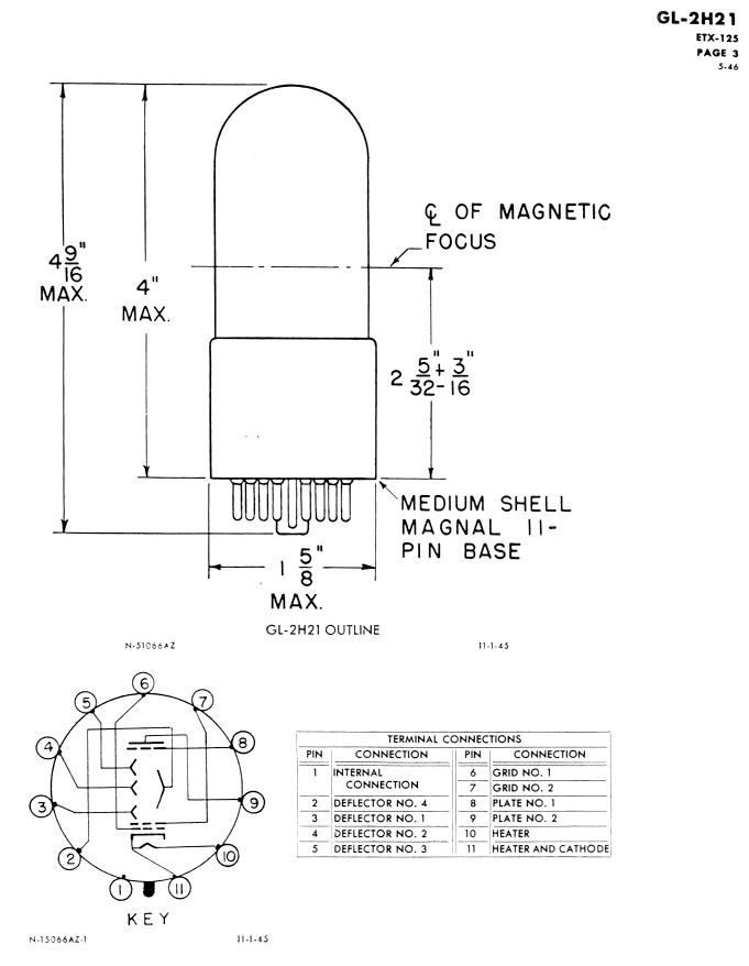
is derated to 250 kHz.) Pinouts are the same but the internal
structure may be just slightly different, judging from the
photos. The 5593 could've easily been called "2H21A," but for
marketing reasons, when the EIA gave up "1A21"-formatted tube
identifiers in favor of "5500"-format, the old scheme looked dated. To swamp you with trivia, "2H21" was a mistake. The RMA/EIA
number assigner must've counted the electrodes, gotten eight "usable
electrodes," and therefore used "H," which was the code for
octodes. Trouble is, there was a much more elegant letter, "T,"
for "storage, radial-beam, and other special deflection-control tubes"
which would've
been a lot more suave. "T" got assigned only once, then abandoned.
I believe that the GE 250 watt FM transmitter used at WGCS used the GL-5593 version of the Phasitron.
Here�s a link to an online tube manual page (with some VERY good closeup photographs of the tube itself) run by Jeremy M. Harmer: http://www.tubecollector.org/5593.htm
So much for the news flash - now to the "standard" Phasitron web page information:
Greetings to all fellow aficionados of obsolete, but brilliant technology. And a special welcome to people who are, or who want to be fascinated by the Phasitron tube!
For those who are unfamiliar with the Phasitron, it was a very clever application of vacuum tube technology to solve a problem: creating a phase modulator that had a very wide (+/- 360 degrees or more) and very linear phase modulation characteristic. This allowed a lower frequency multiplication factor in FM broadcast transmitters that used phase modulation.
In the early days of FM, there were two ways of generating an FM broadcast signal.
One way was to frequency modulate a conventional L/C oscillator. The advantage of this method was that it was very easy to achieve wide frequency deviations. The disadvantage of this method was that an automatic frequency control system was required to keep the L/C oscillator on frequency. This was in the days before frequency dividers and phase locked loops. Frequency control was inaccurate (compared with crystal oscillators) and it was a kludge! One transmitter system made by RCA actually used a motor driven variable capacitor system to keep the transmitter on frequency! Such systems also had a certain amount of inherent time delay in the frequency correction system, which meant that frequency errors would persist for a while before they were corrected.
The other way to produce FM, which was more commonly used, was to produce phase modulation instead of frequency modulation. Phase modulators, unlike frequency modulators, could be used with unmodulated carriers provided by crystal oscillators. This eliminates the frequency control problem, but introduces another: getting a wide enough frequency deviation.
Phase modulation and frequency modulation are close cousins. Frequency modulation is the rate of phase modulation. In other words, the amount of frequency modulation is the time derivative of the phase modulation. In a phase modulation transmitter, as the modulating frequency is increased, the phase modulation stays the same but the frequency modulation increases. In a frequency modulation transmitter, as the modulating frequency is increased, the amount of frequency modulation stays the same, but the phase modulation decreases. This means that FM and PM are really the same thing except for a frequency response issue. So, by applying a 6 dB per octave descending slope to the audio frequency response, FM could be produced by a phase modulator.
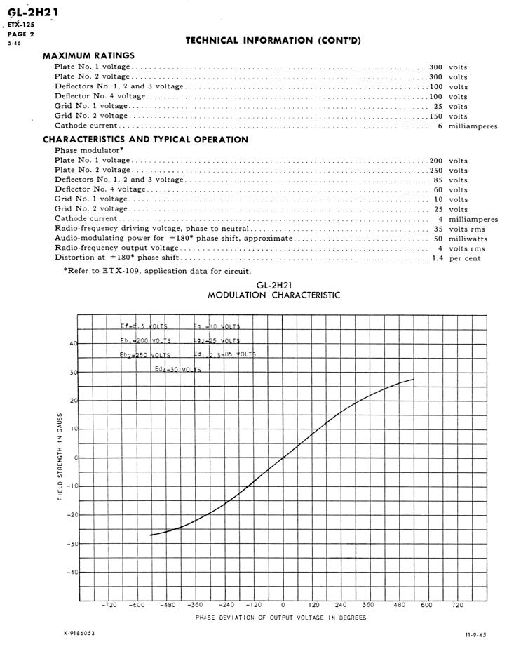
The problem is that the amount of phase modulation (in radians) necessary for simple monophonic audio is the necessary frequency deviation divided by the modulating frequency. (This is also called "modulation index.") So if you want to have 75,000 Hz deviation at 15,000 Hz, you need 5 radians of phase modulation, or about 286 degrees. But if you want 75,000 Hz of deviation at 50 Hz, you need to provide 1500 radians of phase modulation, or 85,943 degrees! Since most phase modulators produce small amounts of phase modulation, the problem of obtaining huge amounts of phase modulation was solved by using frequency multipliers, which not only multiply the carrier frequency, but also any phase or frequency modulation.
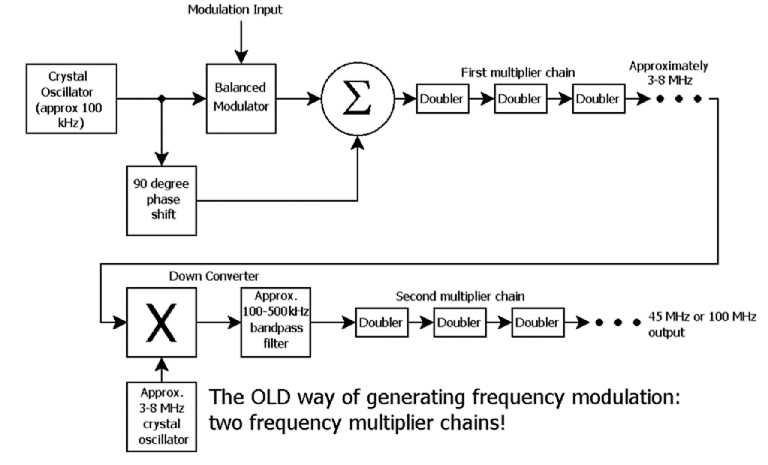
The original Armstrong type FM transmitters used a simple quadrature balanced modulator to obtain FM from phase modulation (PM). They started out around 100 kHz, frequency multiplied up to about 6-8 MHz, then heterodyned the signal back DOWN to 100 kHz, then multiplied back up again to either the 40 or the 88-108 MHz FM bands. The double multiplication chain was necessary because the balanced modulator only produced about 10-15 degrees of phase modulation before its distortion became large. It took a lot of frequency multiplication to turn such small amounts of PM into 75 kHz of FM, especially at low modulating frequencies. Here's a block diagram of the early Armstrong type FM transmitter. (The frequencies and multiplication factors may not be quite correct.)
The Phasitron tube solved that problem by providing huge amounts of phase modulation. The Phasitron was actually a form of CRT in the sense that it used focused electron beams. It produced a thin, focused disk of electrons, flowing radially to a pair of concentric cylindrical anodes. One anode had slots punched in it so that some of the electrons would hit the inner anode, and others would go through the slots and hit the second anode. Then, using a three phase excitation on three sets of radial grid wires, "ruffles" were formed on the electron disk. (Around the periphery of the electron disk, the edge was bent up and down.) The three phases were set up so that the "ruffles" would rotate. The slots in the inner anode were also staggered so that at one instant, most of the electrons would be going through the slots to the outer anode. 180 degrees later, the electrons would miss the slots and hit the inner anode. So, the output from the tube was taken differentially from the two anodes.
Now comes the interesting part. Apply a magnetic field axially to the tube, and the electron disk (and its "ruffles") will twist clockwise. Apply the field the other way, and the electron disk will twist counterclockwise. This produces phase modulation - a lot of it.
So, the Phasitron tube was mounted in a coil that had the station's pre-emphasized audio applied to it. With an audio voltage applied to the coil, the magnetic field was the integral of the applied voltage. So, the phase modulation was also the integral of the applied voltage. That meant that the "phase modulation" coming out of the tube was actually FREQUENCY modulation. The coil, in effect, was converting PM to FM by virtue of its 6 dB per octave slope!
So, the whole system was downright clever. A tube that produced FM, yet with crystal controlled accuracy!
There was an article published in the January 1947 issue of the Proceedings of the IRE (before I was born).
When I was in college, the campus FM station had an old General Electric 250 watt transmitter that used a Phasitron tube. I read the manuals and developed an appreciation for the clever thought and engineering that went into it.
At that time (1970), Phasitron tubes were no longer being made. There were rebuilt Phasitrons which were being sold for $600 apiece - a lot of money in those days. The college FM station had one Phasitron in the transmitter, and two spares on the shelf.
Sometime in the 1940s (no later than 1948 - that date supplied by John Byrns - thanks!), the "Serrasoid" wide-range phase modulator was developed by REL and later used by ITA, Gates, and probably others. That system used oscilloscope sweep-type ramp waveforms to generate large amounts of phase modulation, but that's another story.
Last summer, I got it in my head that I wanted to have a Phasitron tube to sit on my desk and inspire myself to think of weird (but hopefully useful) ways to generate radio signals. I put out the word to the Radio Technology mailing list on Broadcast.Net, and Bill Gillman (WB7RFS) responded. Bill is similarly fascinated with the Phasitron tube, and he has his own Phasitron "trophy" sitting on his shelf. Bill told me where he got his, and I was able to get mine from the same source (Salt Lake Instruments, in Salt Lake City; unfortunately, they're sold out now).
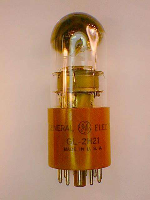
Here's what you came here for - a picture of my Phasitron tube:
And here's a closeup of just the "guts" in the tube:
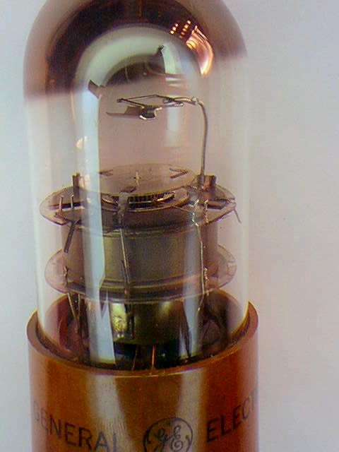
Now if I could just find an authentic Phasitron COIL to go around it!