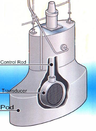
HAIDA'S equipment manifest of the mid 1940's lists the installation of the 144Q Asdic set. Both the 144 and 145 sets were designed to be used with ahead throwing weapons such as Hedgehog but could easily be used with depth charges. This new development in Asdic technology made its service debut in May of 1943. The main features of the 144Q set are described below.GeneralThe Q attachment was an additional Asdic set which required separate transmitting and receiving equipment suitably inter- connected with the main set. Physically, the Q oscillator was mounted beneath the main oscillator and trained with it. It projected a fan shaped beam that was narrower in the horizontal plane than the main Asdic beam but sufficiently wide in the vertical plane to receive echoes at any angle from the horizontal to 45 degrees below horizontal. The beam was only 3 degrees wide on the horizontal plane. Collectively, this new arrangement enabled contact to be maintained with deep targets at short ranges and also minimized the dead zone. The Q beam was transmitted through a window in the bottom fore part of the dome.
This arrangement allowed the Q oscillator to be used at angles of up to 70 degrees from the bow. In shallow water, the Q beam would strike the bottom giving long drawn out echoes that appeared similar to heavy reverberations. This effect made the Q beam appear stronger than the main beam but the effect disappeared in deep water.
Range
The transmission range was selectable between 1000 and 2500 yards.
Frequencies
The main set could operate at any one of a series of fixed frequencies as listed:
| Letter | Frequency (Kcs) | Letter | Frequency (Kcs) |
|---|---|---|---|
| Y | 14 | E | 19 |
| A | 15 | F | 20 |
| B | 16 | G | 21 |
| C | 17 | H | 22 |
| D | 18 |
The Q attachment operated at 38.5 Kcs. To avoid mutual interference between the main set and the Q attachment, the two transmitting circuits were synchronized so that they transmited simultaneously. During reception, Doppler shift was much more pronounced on the Q beam as opposed to the main beam.Oscillator
The Q oscillator was rectangular in shape, completely encased in rubber, and its dimensions were 12.5 inches long by 2 inches wide and 2 inches thick. Within the dome, the oscillator was mounted so it faced downwards at a fixed angle of 15 degrees.
Transmitter
The key operating circuit was completed by the range recorder or by Morse key. Alternately, the circuit could be closed if the send-receive key was moved to the 'Send' position. This action connected the oscillator by way of the tuning panel to the high frequency motor-alternator. A high frequency alternating current was then applied to the oscillator which in turn sent a transmission. The transmission ceased immediately when the key operating circuit was broken.
The motor-alternator set that provided the high frequency current for the oscillator, consisted of a 110 or 220 volt motor driving an inductor type alternator over a range of 4,666 to 7,333 revolutioms per minute. This corresponded to a frequency range of 14 to 22 Kcs. Dual motor-alternators with a change over switch were fitted to allow for maintenance on one unit while the other unit was on-line.
Oscillator frequencies were changed by opening a control box near the motor and moving the 'wandering' lead marked F (field) to a different resistance tap. The selected tap would either speed up or slow down the motor thus changing the output frequency of the alternator. The output was then fed to the tuning panel that consisted of an inductor, a capacitor and resistor. These components formed a resonant circuit that effectively stepped up the output voltage of the alternator to the 2000 volt level required by the oscillator.
It is estimated that the output power of the transmitter was in the range of 300 to 500 watts. The tuning of the receiver to match the actual transmitted frequency was most important - and the facilities to do that were not easy to understand and execute in practice.
Dome
In the retracted position, the dome protruded eleven inches below the keel and was four and a half feet below the keel when extended. A two horsepower motor was required to raise and lower the dome with a provision to do it manually. A set of indicator lamps in the Asdic office indicated the position of the dome -- red was for the working position, green was for housed and red/green for any intermediate state. In the housed position, the dome, the raft, and the oscillator were drawn up to the top of the trunk. The top of the raft butted up against a dermatine seating ring under the top of the trunk, thus making a watertight joint. This allowed the portable cover to be unbolted, in the event that either of the oscillators had to be changed. The procedure would only work if the dome was undamaged.
The Staybrite window of the dome, was aligned with the face of the oscillator so sound waves could be transmitted and received in a 360 degree arc in 5 degree steps. Staybrite was secured over a ribbed section of heavy cast metal and this ribbing is what produced the window effect. Both fixed and retractable domes used Staybrite windows.
Maximum design speed for the dome was 25 knots but on Haida, the maximum working speed was 20 knots. When retracting or extending the dome, it was necessary to check the voltage of the mains supply. In a 220 volt mains' system, the voltage could not drop below 180 volts. If it did, the contactor in the control board could fail to operate thus causing the dome to bump against the end stops and cause damage.
The dome was normally housed for any of the following conditions: when working cables; when working bottom lines; when entering or leaving harbour; when steaming into a heavy sea; if cessation of Asdic operations could be tolerated; and finally, when navigating in shoal water and Asdic is not required for navigation.
AVC Receiver
The Automatic Volume Control (AVC) receiver was a rack mounted, seven tube heterodyne-amplifier, operating in the 10 to 26 Kcs range. Any received sound would disturb the oscillator which in turn produced a weak voltage fluctuation across its terminals. This voltage was then applied through the tuning panel and the send- receive key to the input of the AVC receiver where it was amplified and heterodyned. The A.V.C. output was then fed to the Very/Quick (V/Q) changeover board. Here, the signal could be distributed to the recorder, the loudspeaker, the telephone switches or any combination of these.
Why was an AVC receiver required? When reverberations were received and were extremely loud, they drowned the echo. To overcome this problem, automatic volume control was used. Such an amplifier reduced the amplitude of loud sounds and amplified weak sounds thus producing a 'smoothed out' effect. This in itself is problematic, because echoes would not be distinguishable from reverberations. To overcome the second problem, the amplifier was designed to prevent the AVC from functioning whenever a loud sound was received. This allowed the echoes to escape the smoothing process and made to stand out very clearly against the long (and consequently reduced) sound of the reverberations.
Within the AVC receiver, there was an electronic oscillator whose output signal was mixed with the incoming signal. This is known as the heterodyning process. In the 144Q set, the difference between these two frequencies was 1000 cycles per second. This tone was then passed to the range recorder where it generated a mark on a strip of paper.
Range Recorder
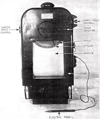
This instrument was designed to visually record sounds received by the oscillator and provide an accurate range plot on paper. At the appropriate time, as determined by adjustments made to the recorder settings, it automatically actuated the release of depth charges or the firing of ahead-thrown charges.
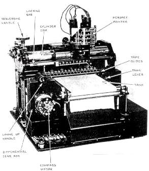 |
| 144Q Range Recorder. (Photo courtesy of the British Admiralty) |
Specially treated paper was driven by a gear mechanism and marked with a stylus. This paper was impregnated with a solution of potassium iodide and starch. Passage of electrical current through the paper from stylus to roller released 'free' iodine. The iodine was then deposited on the paper thus making a record in the form of a brown mark. When installing fresh paper records, it was imperative to minimize the amount of time that the paper was exposed to air. Within the recorder, the paper roll was stored in an airtight container known as a tank.Each roll of paper was 30 yards long and a black warning mark would appear on the right hand edge signifying the approach of the end of the roll. After its appearance, there was still sufficient paper remaining to complete the attack. Alternately, yellow coloured, cadmium-iodide paper could be used in the range recorder. The range recorder was only switched on when investigating a contact and during attack.Bearing Recorder
This instrument indicated the gun bearing when carrying out an ahead-thrown weapon attack against a submarine. An adjustment was provided to make allowance for ship's own speed and the sinking time of the charges. The bearing recorder was used in conjunction with the range recorder from which it obtained the necessary impulses for the paper drive motor.
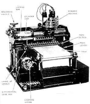 |
| 144Q Bearing Recorder. (Photo courtesy of the British Admiralty) |
Operating the 144Q AsdicHarry Carson provides a detailed explanation on the operation of the 144Q stepping switch. "The stepping switch was a spring loaded, stepped switch, mounted in the centre of the training wheel. When the switch was moved to the right, it would train the oscillator to the right. If the switch was released by the operator, the training mechanism would reverse the direction of rotation and set the oscillator to the same angle as the switch setting. The oscillator would be kept in that direction until the operator heard an echo. At this time, he tapped the switch and continued to do so each time an echo was heard. The oscillator would then be trained off the contact by the control mechanism until the First Operator would receive no echo. Next, the stepping switch was reversed and the training mechanism would reverse direction. The Operator would then tap the switch sharply when the echo was heard. Again, the stepper switch would be reversed and repeated until the bearing 'cut-on' could be determined. Additional repetitions of this procedure allowed the operator to determine right cut-on, left cut-on, extent of target and bearing movement. This data along with information on the echo Doppler would be reported to the bridge.
In the Operations room, the data was plotted on the A.R.L. Plot in preparation for the depth charge attack. If the echo was lost and the 'lost contact' procedure failed to relocate the echo, the A.R.L. Plot would assist the Anti-Submarine Officer (A/S C.O.) in estimating the position of the sub based on the A.R.L. Plot layout. The A/S C.O. would then give the operator a new sector to search. This would still not guarantee that the contact would be found as both the hunter and the hunted may have gone around in circles."
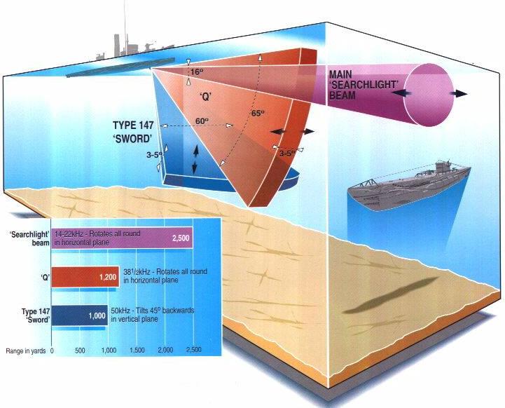 |
| This pictoral illustrates the shape of the detection area for the 144 ASDIC, the 'Q; attachment and the 147 Asdic. Click on graphic to enlarge. (Graphic courtesy of Destroyer Escort Central web page http://www.de220.com) |
The 147 type was a depth finding set that complemented the main Asdic set (144Q and 145Q) and the Q attachment. It's most notable feature was its sword shaped oscillator operating at a frequency of 50 Kcs. Physically, the sword was four to five inches wide and approximately four to five feet long. To prevent interference with the main set, the 147 was mounted ahead of it. When not in use, the sword was stored in a lifting tube mounted within the hull. When deployed, the sword could project a fan shaped beam being narrow in the vertical plane and wide in the horizontal plane. It could be trained up to 65 degrees horizontally and 45 degrees vertically.This new design, which added depth determining capability, could accurately track a target within 20 feet. Another feature was its integration with Squid, an ahead-throwing Anti-Submarine (A/S) mortar. Together, they formed the most effective A/S weapons system of World War II. When an echo was received on a 147B set, the operator would tilt the sword until the echo was lost. He would then reverse the procedure until the echo was heard again, then continue sweeping until the echo was lost on the opposite end of the sweep. Every echo received would then be printed on the depth recorder. A line of light on the depth recorder would indicate the centre of the echo trace. The operator would then look at a calibrated scale and read off the depth directly in feet. From here, the information was used for setting the pistols on depth charge fuzes or transmitted to the Squid mount. When Hedgehog was fitted, depth information was not applied, since this weapon had to strike a solid object before it exploded.New style recorders automatically gave range and direction for steering, while the set itself could automatically set and fire Squid mortars. After the war, it was calculated that a well trained 147 team could achieve a 50 per cent kill rate, nearly nine times that of depth charge system and substantially more than Hedgehog. The 147 set was first tested in March of 1943 and entered service with the Royal Navy in September of that year. It cannot be ascertained when the RCN was informed of this new Asdic type, but discussions for procurement of the 147 did not begin until September of 1943. Eventually 150 of these sets were ordered with the intention of eventually retrofitting all RCN escort ships. A 147F set was fitted on Haida and was complementary to the 164B attack sonar.
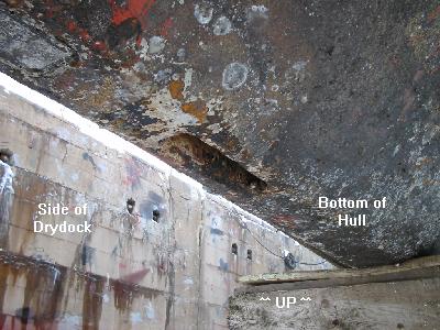 |
| This photo illustrates the opening for the 147 set. The photo was taken when HMCS HAIDA was in drydock in 2003.(Photo by Jim Brewer) |
Harry Carson also adds, "While serving in HMCS Haida from March 15, 1952 to September 24, 1953, the sonar on board was not used extensively in the Korean Campaign as the North Koreans had no submarines. Gunnery was the major weapon of this war although we swept for hydrophone effect especially when sighting Junks along the coast."
Bird class vessels were fitted with sonar set type 163A that had many common components with the type 164AAO. The hull unit and training arrangement were greatly reduced in size and weight due to the small size of the vessel. The dome was tear-dropped shaped and mounted on the end of a streamlined strut. Within the dome, there was a double faced oscillator that could be rotated electrically and either face of the oscillator could be shut off from the sonar control room. Frequency range was 14 to 22 Kcs.
This Asdic set was mainly fitted into frigates and Tribal class destroyers and designed to be used with Hedgehog or Squid (mortar bomb). It incorporated a quartz transducer and the Q2 attachment that is well documented in the 144Q section. In many ways, it was very similar to the 144Q set.The type 164 was a range and bearing finding device that was supplemented with depth data from the 147F set. If fitted on a frigate, then Hull Outfit (dome) number 3 would be used. For Tribal Class destroyers, Hull Outfit 7 or 7A was used. On Haida, both the 164 and SQS-10 transducers were fitted into Hull Outfit 7A. The type 164 bearing repeater was a large mechanical indicator with bearing pointers.
This sonar type, introduced into service in the 1950's, was specifically designed for use by helicopters. It was also known as dipping or dunking sonar. The transducer was enclosed in a small spherical dome that was free flooding. Mounted in the dome was a special type of compass called a flux valve that indicated the true bearing of the transducer on an indicator mounted in the helicopter. The transducer could be manually trained in either direction or automatically clockwise.An operator could select one of three operating frequencies by selecting a screwdriver operated switch on the front panel of the sonar transmitter/receiver.
The AN/SQS-10 sonar was called an azimuth scanning AM type since it transmitted and received omni-directionally. When HMCS Haida was paid off, she was fitted with this sonar type, so it will be discussed in greater detail. SQS-10 sonar was granted 'AN Nomenclature' type number in 1950 and manufactured by Sangamo Electric. Unlike the wartime Asdic sets, this unit did not use a quartz oscillator. Instead, it was replaced with a transducer -- a device that produces underwater sound based on the magnetostriction principle. Unlike the 2000 yard limit of the wartime Asdics, this set could operate out to 6000 yards under ideal conditions when echo ranging.What is Magnetostriction?When an iron rod is placed inside a coil and a direct current (DC) is passed through the coil, the iron will lengthen. This is known as an electromagnet. If the current is reversed, the rod will again lengthen. By substituting alternating current (AC) the rod can be made to vibrate at twice the applied frequency. The amount of lengthening is also dependent upon the material used and it's magnetization properties.
To overcome the doubling effect, a DC polarizing current is applied to the coil. This causes the iron rod to lengthen and stay lengthened by a certain amount. If AC is applied on top of the DC, the rod lengthens even farther during the positive half cycle but returns to its normal length during the negative half. The frequency of the applied AC is selected to be close to the natural resonant frequency of the rod. By bundling multiple electromagnets and attaching the ends of the rods to each of two plates, a pulse of sound can be produced. One plate, which is thicker than the other is known as the base and the other plate is called the diaphragm.
Research indicated that nickel was an ideal material to use in the construction of a transducer since it has a characteristic to retain residual magnetism. This magnetism assists with the production of the polarization field. An alternate method to manufacture a transducer would be to use laminated nickel-iron stampings instead of rods. Each of these electromagnets was called a stave or an element.
Transducer Construction
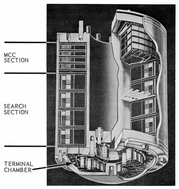
The SQS-10 transducer was cylindrical in shape and operated on the magnetostriction principle. Externally, the transducer is covered with a heavy rubber jacket or boot to keep the internal elements watertight. Electrically, it was two transducers in a common housing. The SEARCH section consisted of 48 vertical staves arranged into four sections. Each stave contained nickel laminations and a polarizing magnet and was electrically independent of the others. Located directly above this array of staves was a second ring of staves that formed the second transducer within the common housing.
This second transducer was used for echo ranging when the target was too deep or too close and the ship was about to pass over it. Since this second transducer permitted the target contact to be held until the last moment, this transducer was called the MAINTENANCE OF CLOSE CONTACT (MCC). The MCC mode was switch selectable from the operators console.
 |
|
|
There was no need to rotate a transducer of this type since the 48 staves covered an arc of 360 degrees. When training the audio system to the bearing of the target, it was a case of simply enabling the staves on which the returning echo or hydrophone effect was the loudest. This was done with the audio scanning switch. A transducer transfer switch selected the normal or MCC portions of the transducer.
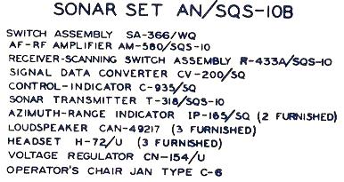 |
| SQS-10 major component listing. (Graphic courtesy Sangamo Electric Company) |
AF/RF Amplifier (AM-580/SQS-10)The primary purpose of the AF/RF Amplifier was to amplify the audio frequency or radio frequency signals received from the 48 staves of the transducer and pass them across the audio and video scanning switches. In addition, the unit contained the keying relay, also known as the send/receive key.
Receiver Scanning Switch Assembly (R433A/SQS10)
This was a cabinet that contained a three channel receiver, the master oscillator and the audio/video scanning system. Pulse lengths from the oscillator were adjustable for 7, 35 or 100 millisecond intervals. One channel of the three channel receiver was used for the audio signal. The other two were used as a twin channel receiver for the video portion of the system. A sum- difference switch on the operators console determined whether they acted as two separate receivers or as one. This affected the display on the CRT mounted in the operators console. In sum, any echo or noise will brighten, but as only as a large mass. If switched to difference, a sharp, clear spot was displayed.
The video scanning switch differed greatly from the audio scanning switch. It consisted of 48 staves rotating at 3000 revolutions per minute, thus giving 9000 scans per minute. Its rotor was divided into a right and left half which permitted the twin channel receiver to be used as either a single unit, or as two separate receivers. Through means of a 2:3 gearing ratio, the rotor was connected to a sweep generator. This generator controlled the rotation of the spot on the cathode ray tube and also the distance that the spot moved from the centre to the outer edge of the CRT. Visually, a small blotch of light was produced at the centre of the CRT and blossomed out into a circle by the time it reached the edge of the CRT.
Transmitter (T318-SQS10)
This assembly contained the power amplifiers for the transducer when echo ranging was used. The 20 Kcs signal produced by the master oscillator was amplified and connected to the transducer by means of the keying relay and the transducer transfer switch. Connecting to this cabinet was the capacitor panel whose operating voltage was 8000 volts. Output power was reduced when operating at close range. Power was also reduced when mutual interference between ships was being experienced.
Signal Data Converter (CV200/SQ)
This instrument, as used by the RCN, converted the relative bearings of signals into gyro bearings. It produced the stern bearing indicator and if the gyro failed, it would automatically change the bearings back to relative.
Control Indicator (C935/SQ)
The control indicator was the operator's position and contained all necessary operating controls. Some of the functions have already been discussed, so readers are referred to an illustration of the SQS-10 operators console.
Azimuth-Range Indicator (IP165/SQ )
This was a slave repeater unit that had its own controls for speaker volume, focus, signal intensity, and CRT intensity. It duplicated what the operator was seeing on his console - a spiral sweep expanding and all the returning echoes or sound spokes (Hydrophone Effect-H.E.) and the bearing cursor. A red plastic disk could be used to protect the phosphor coating on the inside of the CRT in case it was exposed to bright lights or sunlight.
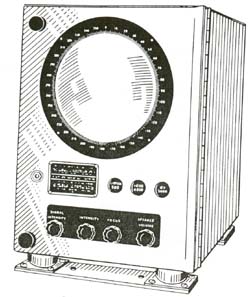 |
| IP165/SQ slave indicator. (Image courtesy RCN) |
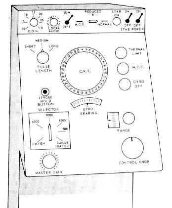 |
| AN/SQS-10 Operators Console (Graphic courtesy of the RCN) |
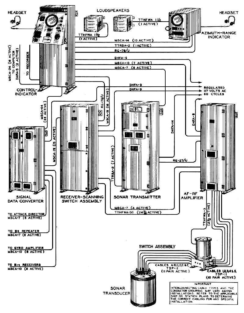 |
SQS-10 system block drawing showing major components. Click on image to enlarge. (Image courtesy Sangamo Electric Company) |
Operating HintsHere are a few operating hints for the SQS-10 sonar quoted directly from the Sonarman Trade Group 1 Manual.
"Should you see an echo anywhere in the CRT, whether it is within the sweep ordered or not, investigate it aurally by training your audio beam on the bearing. If you have difficulty in determining Doppler, switch pulse length to long for a few transmissions. To help distinguish between a wake and or submarine echo, transmit by hand immediately after the instrument has sent out its normal transmission. Wake echoes tend to be mushy, but a submarine will reflect two distinct echoes. If it's necessary to punch through a wake to reach a submarine, it will be easier by switching to a short pulse length."
The AN/SQS-10A was developed in 1953 but an initial procurement by the US Navy was cancelled. Canadian procurements are not known at this time.
Tom Fullerton operated the SQS-10 while serving with the RCN. He recalls the following. "The SQS-10 was my favourite. I participated, with about 20 of my shipmates, in a three week course at the USN Fleet Sonar School Key West FL in July 1963, called something like "Target Aspect Using Scanning Sonar." We were shown that it was actually possible to determine the course of the submarine (+ or - 180 degrees) by examining the shape of the blip on the screen. I found that to be easy using the SQS-10 in close range (1000 yd scale) and with the high definition switch on. I have no evidence that any of the other course participants applied their newly acquired knowledge to that technique.
When we became operational again, I was put in charge of my watch (the "SCO") even though I was still an AB at the time. I would talk over a microphone to the action plot in the Ops Room next door. The contacts were fed automatically into the plotting table using inputs from our sonar and from acoustic info (dunking passive sonar) from the helicopters. Radar ops tracked the chopper's location. There was also a lot of chatter directly from one Ops Room to another when ships were in company. Traditionally when the submarine altered course or changed speed, it would show up perhaps 2 minutes later on the plot. Individuals had no idea of the big picture unless they were watching the plot. The Captain was normally in the Ops Room during these exercises.
When I (using my new-found knowledge, plus echo pitch to eliminate the 180 thing) started to tell them that the target was altering course and calling out new headings in the middle of the course change, the folks
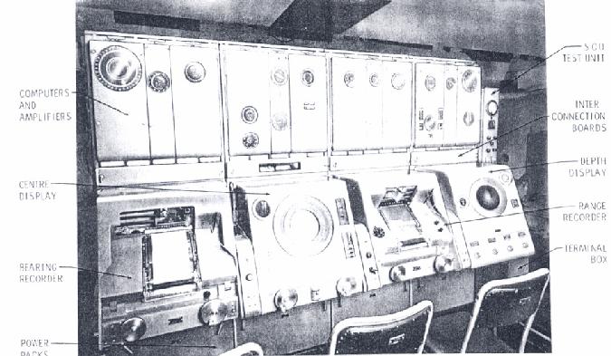
watching the plot were at least 2 minutes behind my information. At first there was total disbelief, then a sense that there was something spooky going on. I ended up with two people who outranked me (a Leading Seaman and a P.O 2nd class) on my watch. The LS constantly complained, but the P2 was an amiable fellow from Prince Edward Island who didn't care a whit.As the "SCO," I stood behind the 5 operators - three on the 502, one each on the SQS-10 and the SQS-503. I had a microphone and a headset. One phone was tuned to the Ops Room, the other was switchable between the three sets. I wandered along behind the operators and watched what they were doing. When we got in within 1000 yds, I would stand behind the SQS-10 operator and throw the necessary switches. I carried a small plastic ruler that I could lay against the blip and then carefully move it to the screen center to determine target course. I also had the mortar firing pistol mounted in the deckhead above me, next to the headphone switch".
The AN/SQS-501 was an auxiliary set designed specifically for identifying submarines lying on the ocean floor where the depth of water was not too great. In the Royal Navy, this set was known as the type 162 or Cockshafer.There were three, fixed, quartz transducers mounted in the forward end of the ships hull. One unit faced port and another faced starboard. The third unit, mounted in the keel, faced straight down. In operation, either the port and keel or the starboard and keel transducers were used. They produced a sound beam at right angles to the ship's fore and aft line. This beam was fan shaped, being narrow in the horizontal and very wide in the vertical plane. A simple changeover switch provided a means of projecting the beam to port or to starboard.
 |
|
|
 |
The recorder produced a shadow trace that gave a reasonably clear picture of the bottomed object. By application of a mathematical formula, it was possible to determine the length and width of the target. The transducers were mounted in hull fittings that were secured on the inside of the ship's hull. Another system equalized the pressure inside the fittings to that of outside sea water. This was accomplished with inter-connecting pipes between the hull mountings and a supply tank that was mounted inside the ship at water level. The liquid used in this system consisted of a mixture of water and glycerine. This prevented freezing and possible damage to the hull mountings in colder climates.
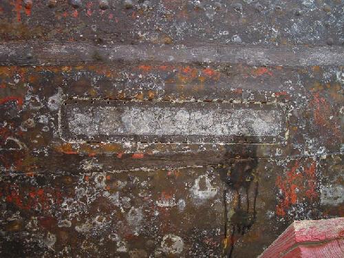 |
| The port or starboard side hull openings for the SQS501 transducer would have looked like this. This photo of HAIDA's hull was taken when she was in drydock in 2003. The hull has just been power washed, hence the lack of paint. (Photo by Jim Brewer) |
AN/SQS-502
By the late 1950's, this attacker sonar, which was a derivative of the British 170 set, became a popular fitting in Canadian destroyer escorts. This was the first set in which sonar and weapon was incorporated so that the weapon was automatically trained thru 360 degrees, the mortar depth and the mortar range automatically adjusted by the sonar set. In this case, the weapon was the Mark 10 mortar. The maximum range of this weapon was 1000 yards with a maximum depth setting of 1,220 feet.The transducer used in this set was of the magnetostriction type and was fitted in any one of six frequency types. It was divided into four squares and secured in a diamond shaped gimbals mounting. The whole assembly was normally fitted in Hull Outfit 7 or 7A. Under operator control, the transducer could be tilted up or down as well as rotated. This transducer transmitted as one unit but received echoes as four separate units. The top and bottom units were used for depth reception while the right and left sections were used for bearing reception.Transmitting
The frequency of transmission would be produced by mixing a fixed frequency produced by a master oscillator with a variable frequency produced by a VFO. The required difference was filtered out in the mixer/pulser unit, amplified in the power amplifier and applied to all four segments of the transducer that were now connected in series.
Video Reception
The incoming signal was received by the four separate transducer segments, amplified, and heterodyned and amplified again for audio reception. This signal fed the audio listening panel and two phase discriminators. One phase discriminator was for the right and left sections of the transducer (bearing) and the other was for the top and bottom sections of the transducer (depth). The phase discriminators caused the blip on the CRT to be left biased, right biased, or centred on two vertical lines depending on where the transducer was pointed in relation to the centre of the target.
Two lines were traced on the face of a CRT from bottom to top. One line represented bearing and the other portrayed depth. When an echo was received, a blip would appear horizontally across both lines. The distance at which it occurred from the bottom was representative of the range. If the blip was equal on both sides of the bearing line, it indicated that the transducer was pointed to the centre of the target. A blip that was larger on the right than left, indicated that the transducer was trained to the left.
 |
|
|
Jack Kilburn recalls this story relating to the '502 sonar. " After basic training, the navy suggested I become a Radioman Special but I wanted off land so I chose Sonar to be my trade. The first ship I was drafted to was HMCS KOOTENAY. One week, while we were duty ship, we received orders to leave Halifax harbour under a cloak of secrecy. We did not know what was going on. After leaving, our No 1 Sonar team closed up on the center display on the SQS-502. Why? - because I picked up a perfect echo coming straight down our beam. I reported it and classified it as a contact. Then came a few chuckles from the Officer behind me who said it was a wreck or something similar. That great old '502 was indicating our ship's speed and also the contact's speed. I said, "the 502 is saying that the wreck is also moving ". Then all hell broke broke loose when everyone realized that I had actually found a Russian nuclear submarine which was off course. This was confirmed with our new, top-secret JEZEBEL [1] system. We sat over the sub for the whole night trying to contact it with the underwater telephone but to no avail. In the small hours of the morning, the sub sent up a bunch of balloons and decided to leave but we were in hot pursuit. While observing the range recorder, the needle went off the paper and the sub was able to outrun us. We were told to be hush-hush about the incident. About 2 or 3 years after I got out of the navy, the incident was reported as news item one night. I must say that SQS-502, a hybrid vacuum tube- transistor design, worked well in its heyday and also in conjunction with the 1011 and the 503 sets. We could outdo the US when it came to sub hunting exercises even in competitions down south".
This was an auxiliary sonar set and was similar in function to the AN/SQS-10 and -11A. It had all around video listening, searchlight type audio listening, and an increased range due to greater power output. A separate presentation of echo pitch was displayed on a separate cathode ray tube that was mounted on top of the operators console. By manipulating video presentation, the ship itself could be represented as being the centre of the bearing and range CRT. Alternately, the target could have been centred in the CRT. The latter made it possible to see the angle at which the target was lying thus making it possible to read the submarine's course.One sonarman recalls "I don't recall any particular problems with the AN/SQS-503 sonar aboard Restigouche, except that it was difficult to fix. The reason was that the schematics largely did not match the set we had. It was rumoured that the '503 had had teething problems, and EDO (Canada) engineers were aboard during construction and trials at Montreal to work things out. They did this by, in some cases (notably the display unit) completely redesigning and rewiring the set to get it to work. I can recall comparing the tube types on one circuit board to the specifications. They weren't even the same filament voltage".
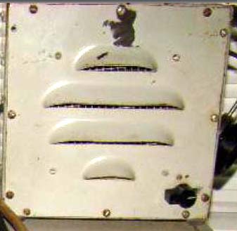 |
| SQS-503 speaker. (Photo by Greg Farrell) |
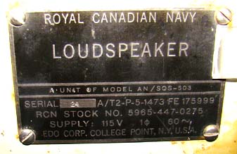 |
| Namplate on SQS-503 speaker. (Photo by Greg Farrell) |
Tom Fullerton adds the following. "The AN/SQS-503 for the Restigouche class was designed and built by EDO Corporation of America. The Canadian government convinced the company into setting up and building the sets in Cornwall, Ontario. The interesting thing about it was that, as far as I know, Canada was the only navy to ever buy that particular model. At the time, the Americans were very much into bottom-bounce sonars".
This device was an underwater communication set, or as it was more commonly refereed to as an Underwater Telephone. It was designed for use on submarines and surface ships to provide amplitude modulated (AM) voice or CW communication through the water using a 8.0875 kHz carrier. AM mode employed Single Side Band (SSB) using the upper side band (USB). The useable range varied between 8,000 to 12,000 yards depending on ship's speed and sonar conditions. That is the range quoted for the 'A' and 'B' variants. Morse code used a fixed audio note of 712 Hz. Personnel stationed on the ship's bridge used a telphone like device when communicating on voice.A small, cylindrical, magnetostriction transducer was fitted in the sonar dome, aft of the main set. A combined receiver-transmitter panel was fitted in the sonar instrument space while the 'sonar set control - remote control unit' (SSC-RCU) was mounted at either the command position or in the operations room. The SSC- RCU contained a power off/on switch for the set, a loudspeaker with volume control, a Morse key, a phone/CW switch and a microphone.
A hand written note on one of the source documents for this device indicates that the RCN ordered 45 sets on the initial procurement. HMCS Haida was fitted with the AN/UQC-1B at the time she was paid off.OTHER DATA
Manufacturers: UQC-1, 1A, 1B RCA , Camden N.J.
UQC-1D Bendix Corp, Bendix Pacific Division, North Hollywood CaliforniaProduction : 1A - March 1958
1B - 1960
1D - 1962
(one Parts Manual for the UQC-1B is dated 1956)Stock Numbers:
'B' variant - NATO 5845-21-041-1681.
'D' variant - NATO 5845-21-041-5083Manuals:
Maintenance Standards for AN/UQC-1, 1A, 1B.
Bureau of Ships. NAVSHIPS 91180.42. Contract Number 71851. RCA. March 31, 1958
 |
 |
| Front view of the receiver-transmitter cabinet with the service panel removed. (Graphic courtesy of RCA Victor) | The receiver-transmitter cabinet with both chassis swung down for servicing. (Graphic courtesy of RCA Victor) |
 |
| This AN/UQC-1 has definitely been in "blue collar" serivce. (Photo courtesy of Destroyer Escort Central web page http: //www.de220.com) |
HULL OUTFIT 7A (SONAR DOME)
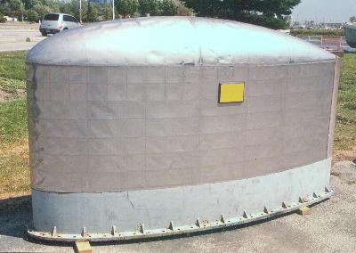 |
| This SONAR dome, actually known as HULL OUTFIT #7A was part of HMCS HAIDAs SONAR system. To protect the transducer(s), which is mounted within the dome, the exterior of the Hull Outfit is clad with a special type of stainless steel called Staybrite. When in operation, the dome is lowered from the hull of the ship using a hoist. It then floods with sea water, thus permitting the passage of the transmitted sound pulse and reception of echoes. (Photo by Jerry Proc) |
The maximum working speed of this dome was 20 knots however, SONAR echoes are very difficult to detect beyond 15 knots because the water rushing by the dome would mask the incoming echos. Any SONAR dome on any ship was normally housed inside the hull for any of the following conditions: when working cables or bottom lines; when entering or leaving harbour; when steaming into a heavy sea; if cessation of SONAR operations could be tolerated; and finally, when navigating in shoal water and SONAR was not required for navigation. Note that the SONAR dome is being displayed in an inverted position. The flange with the bolt holes would normally be secured to the hoisting mechanism.
 |
| This cutaway view illustrates the placement of the transducer in the hull outfit and closly resembles the 123 ASDIC used in Corvettes. (Graphic courtesy of Destroyer Escort Central web page http://www.de220.com) |
761 Echo Sounding Set
Haida's equipment manifest from the mid 1940's indicates that a Model 761 echo sounding set was fitted. To measure water depth, a ship transmits an underwater sound impulse that travels through the sea at a uniform speed. On reaching the sea bed, an echo is returned which is then measured and recorded graphically. The interval of the echo is proportional to the depth of the sea.
 |
| 761 Echo Sounding Set. (Photo courtesy of the British Admiralty) |
The actual depth recorder transducer consisted of two identical magnetostriction oscillator units operating at a frequency of 14.25 Kcs for both transmitting and receiving. These units were mounted in a heavy cylindrical steel tank filled with fresh water or wood alcohol anti-freeze. This assembly was then secured to the inside of the ships plating. The oscillators had no moving parts and consisted of a pack of thin nickel laminations on which was wound a torroidal winding consisting of 24 turns of .036" insulated wire. It was essential for the operation of the oscillators that all air be excluded from between the nickel laminations, so these units had to be specially prepared during the manufacturing process.Reflections from the sea bottom were applied to the receive oscillator which was followed by a two stage amplifier. The output of the amplifier was then fed to a strip chart recorder.NOTES:
[1] Known as AN/AQA-3, "JEZEBEL" was passive, long-range acoustic search equipment.
Contributors and Credits:1) "Jack Kilburn" <sailorjack47(at)hotmail.com>
2) Greg Farrell <gregf (at)pon.net>
3) Tom Fullerton <tfullerton(at)primus.ca>
4) Jim Morrice <jmorrice(at)ns.sympatico.ca>
5) Bob Welland.
April 25/09