GENERAL
- The IFF acronym is derived from the words Identification, Friend or
Foe. Sometimes it was called Radar Identification and Recognition System.
Starting with the MkI system in WWII, IFF intially started with its own
separate equipment and antennas and had some limited direction finding
capability. In later developments it was incorporated to work with the
main main radar search antenna. Not all radars have an IFF
capability. The radars today that usually have IFF are the Air Search
and Surface Search (long range) using the same interrogator. Today,
the IFF interrogator is embedded in the feedhorn (or a secondary antenna
'bolted' to the parent) of the radar antenna and as the radar sweeps and
hits a target it challenges it at the same time. The operator on
the radar set sees an IFF squawk on his PPI. The latest equipment using
the Mk 12 protocol displays all kinds of information to the challenger.
When IFF is being used, the searching radar automatically sends interrogating pulses. This is accomplished by having the IFF dipole antenna mounted across the opening of the feed horn of the radar antenna. The IFF unit in a friendly target will automatically respond with the correct reply and the reply is made visible on the screen of the interrogating radar.
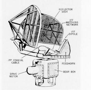 |
| This picture shows the placement of the IFF dipole relative to the main antenna. (Photo courtesy U.S.N). |
- Having the dipole antenna across the feedhorn was not the case from
the beginning. The next section traces the development of IFF from WWII
to present.
IFF SYSTEM HISTORY
- In Britain, IFF was a pre-war development initially destined for installation
on aircraft of the Royal Air Force. Designed by Don Priest and improved
by Bob Carter of the Bawdsey station, the device was housed in an eighteen
square inch box and was carried in the aircraft cockpit behind the pilot.
It was a cumbersome unit for fighter aircraft with little cockpit space.
The unit transmitted a signal to the operator of the Chain Home (CH) radar
to indicate that the aircraft under surveillance was friendly.Failure to
use IFF could cost a pilot his life as evidenced in the Battle of Barking
Creek. This battle occurred in Britain in 1940 when an a CH operator on
the Thames Estuary, not realizing the radar was incorrectly tracking an
aircraft on a 180 degree reciprocal bearing, erroneously identified the
aircraft as an intruder over the North Sea. Fighters were scrambled to
intercept, however they did not turn on their IFF. The investigating fighters
were plotted by a second CH station and reported to Stanmore as intruders.
A second group of fighters was dispatched to intercept the first group.
In the resulting confusion, British fighters fought British fighters and
caused severe damage to a number of machines.
Pilots, who were not familiar with radar, did not appreciate the importance of switching on the IFF. Alongside the switch to turn on the unit was the IFF destruct switch to prevent its capture by the enemy. Many a pilot chose the wrong switch and blew up his IFF unit. The thud of a contained explosion and the acrid smell of burning insulation in the cockpit did not deter many pilots from destroying IFF units time and time again. Eventually, the self destruct switch was secured by a thin wire to prevent its accidental use. During World War II, both metric and centimetric radars proliferated on ships of the major navies. Search radars were joined by fire control sets and ultimately, a ship could locate and destroy air or surface targets in conditions of zero visibility. It therefore became important to be able to identify the targets, or at least distinguish friend from enemy.
The earliest American IFF system was the Naval Research Laboratory (NRL) Model XAE of 1937. It was a shipboard Yagi antenna mounted on a rifle stock that could be pointed at an unknown aircraft. The pilot would turn on his omnidirectional identification beacon and the ship would transmit back an acknowledgement that flashed a light on the aircraft, visible from the ship. The system worked on a frequency of 500 Mcs. This air to ship system was tested in 1938 and operational use began in 1939. In England, quite independently, Watson-Watt conceived a similar device for aircraft identification that became known as the Mk 1 system. Unfortunately, when aircraft were in tight quarters at a distance, it was not possible to distinguish friend from foe. What was needed was a more positive means of identification -- a transponder that would reply to each radar pulse it sensed.
MK I AND MK 2 IFF'S
In 1940, the MK 1 system was introduced in British service. Its details were disclosed to the United States that fall, but this system was already obsolete. Quite independently, the Naval Research Labratory (NRL) had developed a pulse transponder in 1939. To challenge, the radar was switched to a special pulse repetition frequency (PRF) which triggered responses. In US Service, the CXAMM IFF system was considered equivalent to the British Mk II. So far, the radar itself was the interrogator. Since the interrogator and transponder operated on the radar frequency such operation was not satisfactory when many different radars were used.
MK III IFF
The Mk III IFF was Watson-Watt's invention and the precursor of modern IFF systems. IFF challenge and response were to occupy a separate, specialized band (A-Band; 165 to 185 Mcs or 157 to 187 Mcs, depending on the reference text). It was adopted as the standard Allied IFF of World War II and remained in US service for sometime after the war. An important design criterion was to ensure that the returning signals gave an accurate indication of target bearing and not merely of target range. The solution was to locate the IFF interrogator on the radar antenna, rotating with it to give directional indications. The same device would also receive the response. This was known as an 'interrogator-responsor' system. Mk III was distributed to all Allied forces including the Soviet Union. From a post-war point of view, it could be considered thoroughly compromised.
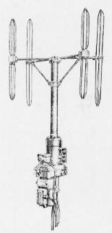
Because the system relied on active responses from other ships and aircraft, there were no problems with sea returns. It was possible to use vertical polarization, thus giving better vertical coverage. The transmitters also required much less power for a given range so the fitting of IFF presented few space problems. Initially, the interrogator aerials consisted of directional Yagi arrays mounted on a horizontal U bar, but in 1944, the most commonly used aerial system consisted of four, broad-band cage dipoles in a rectangular configuration and capable of power rotation.
Reports on the value of IFF varied, according to the theatre of operations. They ranged from "worked very well" to "never saw it used once in two years at sea."
MK IV IFF
Back in the United States, the NRL designed an alternative system designated Mk IV. It differed from the Mk III system by employing separate frequencies (470 and 493.5 Mcs) for challenge and reply. Mk IV was generally held in reserve during the war in case the Mk III was compromised. A few were used in the Pacific theatre at the end of the war. In Europe, it was not used due to its closeness to the frequency of the German Wurzberg radar that operated at 550 Mcs. A German radar operator might discover IFF pulses from Allied aircraft, thus compromising the system. Due to its higher operating frequency (G-band), Mk IV had greater directivity and the typical beam width was 7 to 10 degrees.
MK V IFF
Mark III was an interim measure and the NRL was directed to produce a new system that became Mk V/UNB (United Nations Beaconry). Wider transmitter and receiver frequency separation permitted the use of higher gain antennas and higher frequencies (950 to 1150 Mcs) made for better directivity. Twelve channels were made available within this range as an anti-jamming measure. Signals were coded to permit, for example, identification of one among several 'friendlies'. On a Plan Position Indicator (PPI) display, transponder coding would be displayed as a dot and dash elongation (radially) of the target pip. The first Mk V systems appeared in August of 1944 but the system did not complete service evaluation until 1947-48. Mk V was considered successful but few were produced. Installations were confined to CVB's and fleet carriers where it was important to be able to track and identify fast targets such as jet aircraft. As an example, Mk V could identify a jet aircraft flying at 175 mph at 20,000 feet. An attempt was made to re-design and simplify the Mk V system. This was designated as Mk VI.
MK X IFF
The follow up system to Mk V was Mark X, a system developed in the USA. At first, this did not mean a jump from the fifth to the tenth Allied IFF system. The X denoted an experimental system and after it went into production, it assigned the Mk X (ten) nomenclature. There were problems with the Mk V system. It used a universal 'code of the day' to distinguish friend from foe but the NRL considered this a serious, potential security risk. Another danger in the Mk V was enemy use of Allied IFF to identify our own craft. By July 1952, the Mk X system started operational use in 50 per cent of the US Navy. The balance of the fleet was to be converted by January 1954.
The Mk X IFF system sends a pulsed secondary signal from its Interrgator along with the main radar signal. This in turn is received by a Transponder situated in the craft under observation. The Transponder then sends back an appropriate reply that is detected by the Interrogator and distributed for display. Separate pre-set frequencies are used for interrogation and reply; 1030 MHz for transmission and 1090 MHz for reply. Normally, the IFF antenna will rotate in synchronism with the main air warning radar thus enabling the responses to be superimposed on the radar picture.
Three modes of operation are available for General, Personal and Functional identification. The mode of operation is determined by the spacing between the two 1 microsecond pulses which constitute the interrogating signals. Spacings employed are 3, 5, and 8 microseconds for modes 1, 2 and 3 respectively. The transponder reply to each of these interrogations is a single one microsecond pulse except in the case of an aircraft in which the reply to a mode 2 challenge is two, one microsecond pulses spaced 16 microseconds apart. In addition, the aircraft has the facility of an emergency reply consisting of four, one microsecond pulses spaced by 16 microseconds between adjacent pulses. A transponder will always reply to a mode 1 interrogation but replies to interrogation in modes 2 and 3 are optional. This is dependent upon the setting of appropriate switches on the transponder control panel. When set to emergency mode, the aircraft transponder will transmit the four pulse reply to all modes of interrogation.
MK XII IFF
Mark X did not provide real security. Its interrogation pulse was not coded. There was always a possibility that an enemy might use Mk X interrogation pulses to induce US aircraft to identify themselves and then use the aircraft's IFF system as a homing beacon for missiles. As early as 1951, the NRL had developed a vacuum tube binary coder but it was too massive for airborne use. Transistor technology improved matters. By 1956, an American tri-service group had been formed to implement what has now become the Mk XII system, the current system in use.
This is a fully cryptographic system so even if the enemy had full knowledge of the system design, it cannot be used unless the correct interrogation and response codes are known.
EQUIPMENT TYPES
- British IFF systems were coded into two series during World War 2;
the 240 designation was used for interrogators and the 250 series for responders
and beacons. Only IFF equipment types used aboard HMCS Haida are described
here.
242 IFF Interrogator Series
Type 242 IFF series interrogation equipment was fitted on RCN ships in conjunction with Type 291 and Type 275 radar sets to provide 'A' band interrogation using the standard Mark III IFF system. Interrogators could function anywhere in the 165 to 185 MHz band, but were normally used around 179 or 182 MHz (1.8 to 1.6 metres) at a power output of 1 kilowatt. The pulse repetition frequency was 125 or 50 pulses per second and the pulse length was 6 microseconds. When used with radar types 291, the 242 was fitted with aerial outfit 'ASD'. This aerial had an omni-directional radiation pattern. Type 242 was first introduced into service in 1943. The pulse repetition frequency of the main radar was counted down in ratios of 4:1 or 10:1 in the modulator which then fired the interrogator transmitter. Simultaneously, a secondary trace, displaced from the main trace was displayed as an 'A' scope presentation. Interrogator signals received by the responsor unit were displayed on this secondary trace as inverted signals along with the normal radar echoes. Correspondence of the interrogator pulse and the radar echo identified the target. The associated shipborne transponder was the type 253 or the Mark III IFF when fitted on an aircraft. Haida was fitted with the 242WC and 242WS types in the mid 1940's.
242 Type Interrogator
- Types: 242 was used with types 271 and 275 radar
242M was used with radar types 276/277 and 293.
242P/Q were used with radar sets 960/982/983.
Frequency band: 165 to 185 or 159 to 189 MHz (covers all variants)
|
|
| 242 Data Sheets |
| 242 M, P and Q Data Seets |
| 242 Handbook excerpt. |
The pulse repetition and pulse length varies depending on the types of radar that the 242 was used with. 242M is similar to that of type 242 except for some minor modifications. Transmitter power was now selectable between low and high power outputs (2 kw or 10 kw) and the output frequency could be varied across a 30 MHz wide band. A pre-amplifier was incorporated in the transmitter unit that increased the responsor range and the transmit/receive (T/R) switching arrangements were improved. When the 242M operated in conjunction with the 276/277/293 radar types, it was fitted with aerial outfit 'ASS'. This aerial consisted of four broadband vertical dipoles with power rotation.
 |
 |
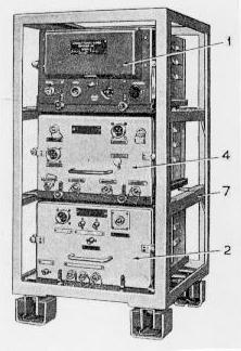
| 242 Interrogator - Component Parts. 1.W4790 responsor unit 2.7AD transmitter 4. W6332 Modulator and mixer. (Photo courtesy of the British Admiralty) | 242Q. The power output of the Q variant was 2 or 10 kw. (Photo courtesy of the British Admiralty) |
 |
 |
| Close up view of 242M Aerial Outfit ASS.
(Photo courtesy of the British Admiralty) |
Aerial Outfit 242M on HMCS HAIDA as see on her first tour of duty in Korea. (Photo courtesy RCN) |
253P Transponder
- Type 253P was a shipborne transponder, compatible with the Mark III
IFF system and operated in response to triggering pulses from any interrogator
or radar set in the same frequency band. When triggered, Types 253P/Q responded
with various coded signals as required for the purposes of normal interrogation
or ship-to-ship identification or homing. This set could operate in the
157 to 187 MHz band but normally operated at 182 MHz for ship-to-ship identification
or when used as a beacon facility. In a normal fit, aerial outfit 'ASH'
was used. For installation aboard coastal craft, aerial outfit 'ANT' was
used. Normally the power output was 10 watts. A low power setting of 0.75
watts was available as an anti-direction finding measure. The pulse repetition
frequency was triggered by the receipt of signals from interrogators of
radar sets. This was limited only by a 300 microsecond period of quiescence
between each transmission. The pulse length of the output signal could
be set for narrow (6-10 us), wide (17-25 us), or distress mode (80 us).
| 253P and Q data sheets |
 |
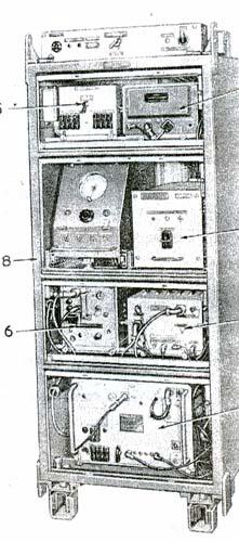
| 253 Transponder - Component Parts (Photo courtesy of the British Admiralty) |
Types 253P and 253Q were similar except that type 253Q was mounted in a resilient steel cabinet. By operating the buttons marked 'I', 'A', and 'B' on the code selection unit, the following operating conditions were permitted:I: Normal Mark III IFF responses (sweeping 157-187 MHz every 2.8 seconds). Six codes were available by selection and each code consisted of four transmissions using narrow and wide pulses. A complete code was transmitted once every 11.2 seconds. A special extra wide pulse was available for distress purposes.
A: Alternate normal IFF codes consisting of four narrow pulses for 5.6 seconds followed by 5.6 seconds of Identity Code on a fixed frequency of 182 Mcs. This code consisted of two letters that could be of any combination of nine narrow, wide or blank pulses which were selected by means of the nine switches on the Code Selection Unit.
C: Chopped response on the frequency of 182 MHz. The response was mechanically interrupted for 40 milliseconds every one-fifth second to distinguish it from a normal code.To limit mutual interference, the antenna for type 253P was situated at least 12 feet or more from the nearest interrogator antenna on a ship. Haida was fitted with the type 253P transponder during the mid 1940's.
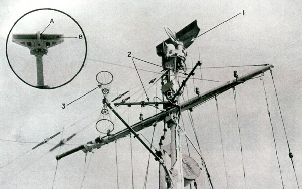 |
| Item 1 - 268 Radar; Item 2 - Interrogator type 242; Item 3 - 253 Transponder. (Photo via Øyvind Garvik) |
MODERN DAY IFF
Modern day IFF systems are basically Question/Answer systems. An interrogator system sends out a coded radio signal that asks any number of queries, including: Who are you? The interrogator system is frequently associated with a primary radar installation, but it may also be installed aboard a ship or another airplane. The interrogation code or challenge, as it is called, is received by an electronic system known as a transponder that is aboard the target aircraft. If the transponder receives the proper electronic code from an interrogator, it automatically transmits the requested identification back to the interrogating radar. Because it was developed as an adjunct to the primary echo-type detection radar and is usually used in conjunction with a primary radar, the IFF system is also known as secondary radar.
Modern IFF is a two channel system, with one frequency (1030 MHz) used for the interrogating signals and another (1090 MHz) for the reply. The system is further broken down into four modes of operation, two for both military and civilian aircraft and two strictly for military use.
Each mode of operation elicits a specific type of information from the aircraft that is being challenged.
Mode 1, which has 64 reply codes, is used in military air traffic control to determine what type of aircraft is answering or what type of mission it is on.
Mode 2, also only for military use, requests the "tail number" that identifies a particular aircraft. There are 4096 possible reply codes in this mode.
Mode 3/A is the standard air traffic control mode. It is used internationally, in conjunction with the automatic altitude reporting mode (Mode C), to provide positive control of all aircraft flying under instrument flight rules. Such aircraft are assigned unique mode3/A codes by the airport departure controller. General aviation aircraft flying under visual flight rules are not under constant positive control, and such aircraft use a common Mode 3/A code of 1200. In either case, the assigned code number is manually entered into the transponder control unit by the pilot or a crew member.
Altitude information is provided to the transponder by the aircraft's air data computer in increments of 100 feet. When interrogated in Mode C, the transponder automatically replies with the aircraft altitude. Ground interrogators normally interlace modes by alternately sending Mode 3/A and Mode C challenges thus receiving continuous identity and altitude data from the controlled aircraft.
A timing diagram which shows the timing of the pulses for various IFF modes. (Graphic courtesy Litton Systems) The code signal sent by the interrogator system consists of two pulses spaced at a precisely defined interval. (A third pulse that has nothing to do with the coding of the query is actually used for interference suppression reasons.) In Mode 1, the interval between the first and last pulse is 3 microseconds; in Mode 2, it is five microseconds; in Mode 3/A, it is eight microseconds; and, in Mode C, it is 21 microseconds. The airborne transponder contains circuitry that discriminates between these various timings and automatically sends back the desired reply.
The transponder replies are also in the form of a pulse, though in this case, there are 12 information pulses that are digitally coded as "ones" and "zeros." The total number of reply code combinations therefore, is 4,096. The reply codes are entered by means of four code wheels on the transponder control unit. The reply pulses generated by the transponder are decoded by the interrogating system and are typically displayed as needed on the primary radar scope near the blip that represents the aircraft that has been challenged. Thus, the aircraft controller can monitor the track of each aircraft through his zone and know its identity, altitude and position at all times.
The original reason for IFF systems came about was to identify friendly forces in a battlefield environment. For that reason, it is essential that hostile forces not be able to use the system to identify themselves as friendly even if the physical IFF equipment should fall into their hands.
The secure mode is used exclusively for military purposes. This mode uses a very long challenge word which contains a preamble that tells the transponder it is about to receive a secure message. The challenge itself is encrypted at the interrogator by a separate device that uses various mathematical algorithms to put it in a secure form. The transponder routes the ensuing challenge to a separate device that uses the inverse algorithms to decode the challenge. In effect, each challenge is telling the transponder to respond in a certain way. If the transponder cannot decipher the challenge, it will not be able to respond in the proper way and thus will not be identified as a friend.
To prevent unauthorized use of either the interrogation equipment or the transponders if they should fall into hostile hands, a key code must be periodically entered into each device. To eliminate the chance of a random guess by a hostile target corresponding with the proper response, each identification consists of a rapid series of challenges each requiring a different response that must be correct before the target is confirmed as a friend. A very high degree of security to the identification system is ensured through the use of key codes and powerful cryptographic techniques.
[Acknowledgments to Litton Systems the information on modern day IFF].
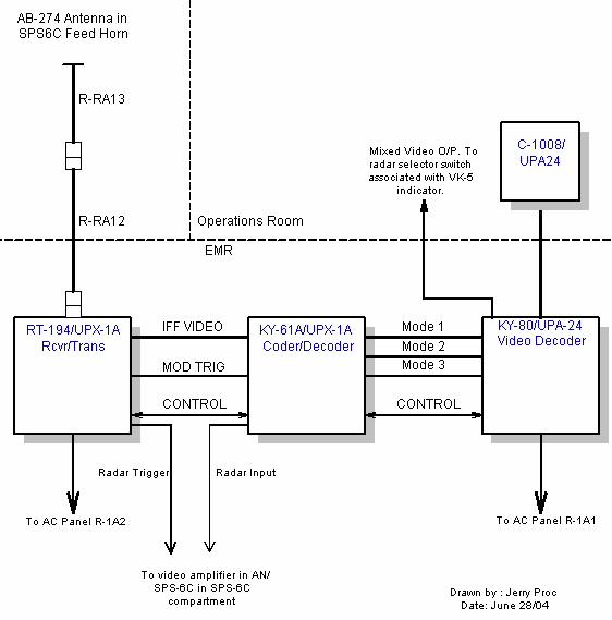
When HMCS HAIDA paid off, this was her IFF fitting. As information becomes available, more details will be provided. Unless otherwise noted, all the equipment was fitted in the EMR compartment. * AN/UPA-24 /KY80 IFF Video Decoder
* AN/UPA-24 /C1008 Radar Set Control (in Operations Room)* AN/UPX-1A /RT-194A IFF Receiver-Transmitter (for IFF dipole in front of SPS-6C feed horn)
* AN/UPX-1A /KY-61A IFF Coder/Decoder
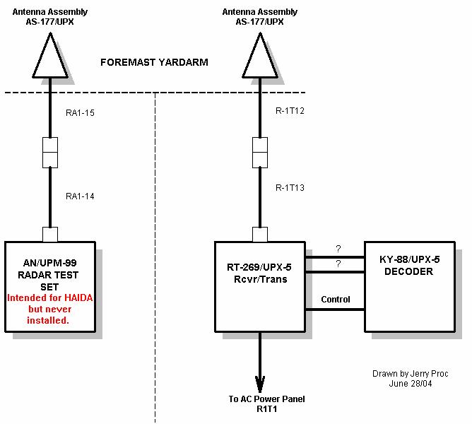
* AB-274 IFF Dipole antenna assembly in front of SPS-6C feed horn* AN/UPX-5 /RT-269 IFF Receiver-Transmitter (for dedicated IFF antenna on foremast yardarm)
* AN/UPX-5 /KY-88 IFF Decoder
* AS-177 Antenna Assembly (dedicated to UPX-5). 1090 mHz TX/ 1030RX* AN/UPM-99 Radar Test Set
* AS-177 Antenna Assembly (dedicated to UPM-99)These devices were shown on the ship's drawing but were never installed:
* AN/UPA-38 /KY-136 Video Coder
* AN/UPA-38 /C1407 Radar Set Control (in Ops Room)
Haida's IFF Interrogation Initiation System Haida's IFF Interrogation/Response System RT-194A/UPX-1
RECEIVER/TRANSMITTER
F. Oorschot, from the Netherlands provides a UPX-1 description."The UPX series were used on the destroyers and frigates of the Dutch navy in the years 1950 to 1970.
UPX-1 was the IFF (Mk X) interrogator; Tx Freq. 1090 Mc/s, Rx Freq.1030 Mc/s. Average power - 1 kw. using Modes 1, 2 and 3. Mode 1 and 2 was a naval-airforce mode. Mode 3 was also a airborne civilian mode. The time between the two send pulses depended on the mode. Mode 1 was 3 usec. Mode 2, was 5 usec while Mode was 3.8 usec. With the code-selectors, you could select a video code that was filtered for a display on a PPI screen.
With the big switch, in the middle and under the UPX-24, you could select the kind of video for the display.
The IFF antenna was fitted on the feeder of a long range early air warning radar (L-band). Trigger for the transmitter came from same radar. The UPX-1 transmitting mode was also controlled by the AN/UPX-24".
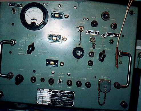
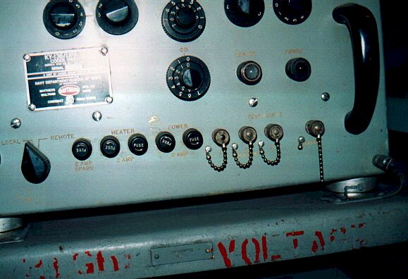
RT-194/UPX-1 (Photo courtesy Destroyer Escort Central page, http://www.de220.com) KY-61/UPX-1 CODER-DECODER
KY-61/UPX-1 (Photo courtesy Destroyer Escort Central page, http://www.de220.com) RT-269/UPX-5
USN Ref - 98579,98825. Circa 1956. Receiver-Transmitter. No photo or info available.
Decoder - No photo or information available at this time. KY-88 - UPX-5
KY-200/UPX-12 The KY-200/UPX-12 was a unit of transponder set AN/UPX-12. Not fitted on HAIDA but used by the RCN. Very similar to the UPX-1 except for the handles and the left side of the panel below the meter. (Photo by Richard Brisson - used with permission)


|
|
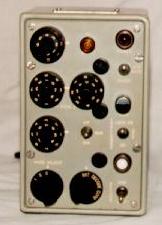 This was the control head for the group video decoder. It controlled the
mode of transmission ( ie mode 1, 2 or 3) and the 'squawk' code assigned
to each particular ship. (Photo by Jerry Proc)
This was the control head for the group video decoder. It controlled the
mode of transmission ( ie mode 1, 2 or 3) and the 'squawk' code assigned
to each particular ship. (Photo by Jerry Proc) |
|
|
 |
|
|
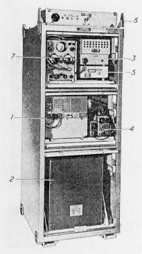
AN/UPM-99
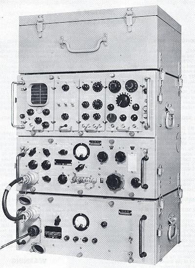 |
| From bottom to top: PP-2391 Power Supply; SM-189/UPM99 Code Simulator ; TS-1253-UP Radar Test Set; CY-1156/UPM-4 Accessory Box. The TS-1253 unit can function separately since it has an internal power supply and incorporates the functions of a precision oscilloscope and SlF code generator. |
Radar Test Set AN/UPM-99 is designed for testing and performing corrective maintenance on IFF equipment of both the Mark X and SIF (Selective Identification Feature) type. It can also be used for making various tests required for maintenance of other radar equipment operating within the 925 to 1225 mHz frequency range.
The entire test set incorporates 88 vacuum tubes and 72 solid state diodes and was introduced in 1960.
- Jan 20/08