The existence of this system and the physical properties of the Electrofile unit (less cards and coding keys) are UNCLASSIFIED. The principle of operation of the AN/ULX-501 system including the keyboard coding of the Electrofile unit is CONFIDENTIAL. The Emitter parameter information contained in CFP 246 (1) and (2) and CFP 247 is SECRET.
INTRODUCTION
In 1966, after a Canadian Forces Headquarters (CFHQ) technical study into existing radar identification systems, notably those in the Royal Navy and the USN, approval was given for the RCN to procure some 50 militarized "Electrofile" units and to develop a radar identification system for the Canadian Maritime environment. During the next two years, several variants were developed and prototype systems evaluated. As a result of these trials, the present AN/ULX-501 has evolved and is now being fitted in the Fleet.
The AN/ULX-501 is designed around the AN/WLR-1C countermeasures receiver and the emitter parameters derived. therefrom. This has determined the fundamental design philosophy behind the AN/ULX-501, for it is axiomatic that no identification system, however sophisticated or computerized, can with certainty improve upon the raw parameter data obtained from the associated intercept system. It can only process the information it is given.
Hence. the problems associated with an identification system invariably relate to the intercept equipment and the precision of its parameter measurements. This is important in the understanding of the present AN/ULX-501 system.
GENERAL DESCRIPTION
The following items comprise the AN/ULX-501 system:
(a) Two NEL (Northern Electric Ltd) Model 100 "Electrofile"
units - (Unclassified)
(b) Two card trays, capacity each having a capacity of 1000 cards -
(Unclassified)
(c) One set each of cards CFP 246 (l) and CFP 246 (2) - (SECRET)
(d) One copy of CFP 247 "Radiation Characteristics of Electronic Equipment
for the Canadian Maritime Environment" (SECRET)
The AN/ULX-501 is a single stage direct entry retrieval system using
two Electrofile random access selector units (Figure 1) to provide rapid
identification of probable sources of intercepted RF transmissions which
have been analyzed.
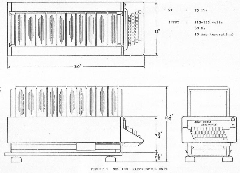 |
| Figure 1 - Electrofile physical dimensions. (Click to enlarge). |
The two Electrofile units comprise a low band covering frequencies from 0 to 7600 MHz and a high band covering from 7601 MHz and up, a total of approximately 1800 coded cards. The cards contain data on all emitters listed in CFP 247, "Radiation Characteristics of Electronic Equipment for the Canadian Maritime Environment".
Any RF transmission intercepted and analyzed on the AN/WLR-1C receiver
will give some combination of frequency, PRF, pulse width and scan rate
information. This information is entered directly on the keyboard of the
appropriate Electrofile unit (Figure 2).
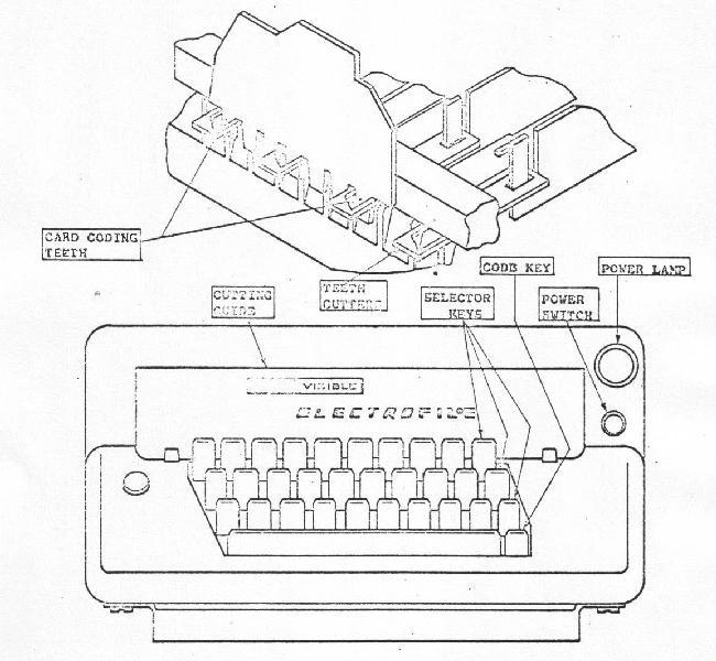 |
| Figure 2 - Coding and Selecting Unit. (Click to enlarge). |
If all four parameters are entered and the operate bar is depressed,
a card will be raised, (Figure 3) listing all known threat emitters and
all friendly maritime emitters with these characteristics and also emitters
which may have been intercepted due to AN/WLR-1C parameter measurement
tolerance. If less than four parameters are entered on the keyboard, a
number ot cards containing the entered parameters plus all combinations
of the omitted parameter(s) will be raised for scrutiny.
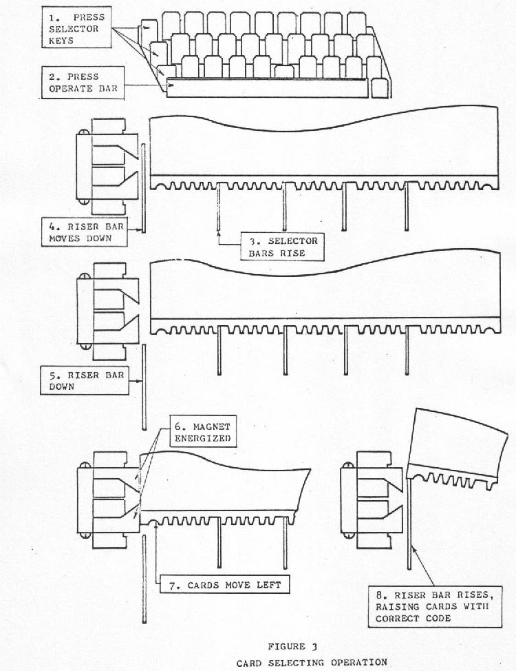 |
| Figure 3 - Card Selecting Operation. (Click to enlarge). |
ELECTROFILE TYPE NEL 100
The Electrofile unit is designed to mechanize a card filing system, making it possible to extract cards by a keyboard operation, eliminating the necessity of sequence-filing the cards. The filing unit consists or a coding and selecting unit, a card carrying tray and specially designed cards.
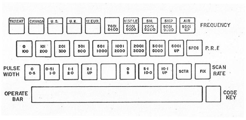
The coding and selecting unit has three rows of ten keys. The first
row is used to enter the frequency, the second row for the P.R.F. and the
third row the pulse width and scan rate or type of emitter. Low and high
band keyboards are shown in Figures 4 and 5.
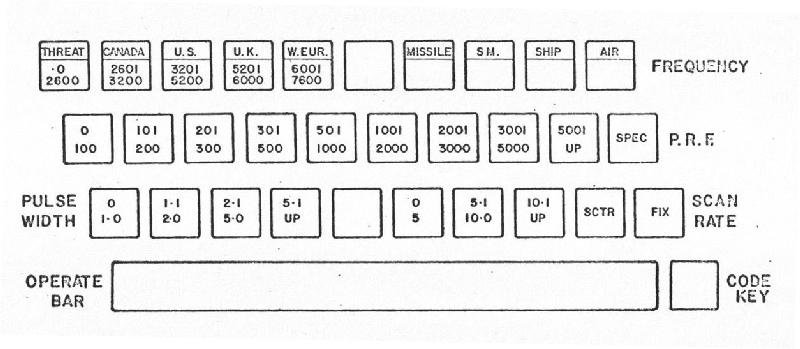 |
| Figure 4 - Keyboard Arrangement, Low Band. (Click to enlarge). |
 |
| Figure 5 - Keyboard Arrangement, High Band. (Click to enlarge). |
The first row serves another function by selecting keys two at a time it enables the retrieval of selected equipment lists. When a key is depressed it raises a selector bar under the cards into the coding strip at the bottom. When the magnet draws cards over to be raised, only cards with appropriate coding tabs removed will be selected.
ELECTROFILE CARDS
The cards are manufactured with a coding strip at the bottom. This strip contains 30 coding teeth and 2 semi-circular aligning cut-outs. The aligning cut-outs rest over rounded longitudinal bars in the tray when the tray is out of the unit. When a tray is in position for selection, the cards are held above the aligning bars. The coding is carried out by the removal of some of the teeth in accordance with a selected code table. The selector unit, which combines both the coding and selecting operations, extract. any card or cards which conform to the code setup by the depressed selector keys and raises these cards above the level the unwanted cards. As the selection of a card is effected regardless of its sequence in the tray, sequence filing is not necessary. The machine has a truly random access memory. Among the advantages of the AN/ULX-501, the following may be cited:
a) The equipment is "fail safe". If, for example. the teeth on the card selected have been bent. mutilated or broken off altogether, the card, when addressed will appear. This is a design feature of the Electrofile Unit.
(b) With a total of 30 keys which can be used in any combination, a large number of specific addresses can be devised and used. In the AN/ULX-501 this use of combination keys is minimized in order to retain the simplified single key direct entry approach to the four basic parameters.
(c) The identification process is completed in less than ten seconds from the time the first key is pressed.
(d) Each Electofile unit contains the complete permutated set of equipment cards. This ensures that, regardless of the permutation of possible parameters, a card will appear. It may not have any emitters if none exist within that four dimensional vector, but it will confirm that the equipment is functioning properly.
(e) New emitters may be entered directly on the coded cards. No special tool or processing is required. If a card becomes mutilated, a new one can be made quickly. Coding a new card takes less than ten seconds, using the built-in die set operated directly from the keyboard.
(f) The machine will operate satisfactorily under any normal, condition of pitch and roll. The keyboard is addressed directly, with no special coding to be remembered by the "seasick sailor".
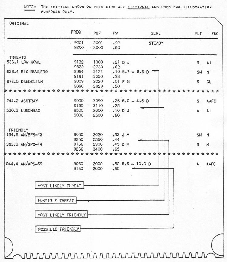
As shown in Figure 6, the emitters on each card are divided into four groups, namely:
(a) Most likely threat
(b) Possible threat
(c) Most likely friendly
(d) Possible friendly.
Those who have studied the problems associated with radar identification realize that tactical identity is not a certainty, but only a probability. One of the uncertainties results from the tolerances associated with the AN/WLR-1C equipment. The emitters are therefore grouped as above, where (a) and (c) do not include AN/WLR-1C tolerances, while (b) and (d) do.
The operator scans the card from "High Threat" to "Low Friendly". A
sample blank Electrofile card is shown below.
 |
| Figure 6 - Sample Equipment Card. (Click to enlarge). |
CFP 247 RADAR INDEX
The 1800 coded cards which are mounted in the two Electrofile units contain all emitters listed in CFP 247 (SECRET).
These total some 282 radars operating in a combination of 547 modes. The positive identification of modes rather than radar types is important, since the switching of a radar from one mode to another can reveal vital tactical information.
Identity numbers are allocated in blocks to assist in the identification
of radar platforms and origins as follows
| FRIENDLY ( 001- 499) | HOSTILE (500-899) | |
| Airborne 001 - 099 | Airborne 500-559 | |
| Submarine 100-199 | Ground 560 - 579 | |
| Surface Ships 200 - 499 | Submarine 580 - 629 | |
| Missiles 630 - 899 | ||
| Surface Ships 670 - 899 |
In addition to the main listing of all emitters with all their parameters, CFP 247 contains the following for quick reference:
(a) Median Frequency Order Listing of all emitters.
(b) Median PRF Order Listing of all emitters.
(c) Threats - Listings in Alphabetical Order
{d) Friendly - Listings in Alphabetical Order
The last two listings also contain relevant remarks to aid the operator in the identification process.
SUMMARY
The AN/ULX-501 provides the operator with a fast, random access identification system. Its limitations are basically those of the AN/WLR-1C countermeasures receiver. An informed and motivated Electrofile operator can, by deductive and intuitive processes, perform some filtering of the machine responses himself.
The machine is there to process the intercepted emitter through the parameter cells to the stage where it can either present the solution, or offer the operator a number of alternatives from which a tactical decision can be made.