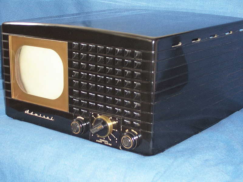
Trade Name:   Admiral

Manufacturer: Admiral Corporation Chicago, Ill.

Model Year:   1949

Type Set:     Television Receiver B/W

Tubes:        Sixteen

Picture:      7 inch Black & White

Tuning Range: Channels 2 thru 13

Cabinet:      Bakelite Table - Black
V701 6AG5.....1st RF Amp          V9  6AU6.....Video Amp
V702 6J6......Mixer/Osc           V10 5Y3......Low Voltage Rectifier
V1   6AU6.....Audio IF Amplifier  V11 6SN7.....Sync Seperator/Vert Osc
V2   6AL5.....Ratio Detector      V12 6SN7.....Sync Amp/Horz Osc
V3   6SQ7.....Audio Amplifier     V13 1B3......High Voltage Rectifier
V4   6AS5.....Audio Output        V14 6V6......High Voltage Osc
V5   6AU6.....1st IF Amp          V15 6SL7.....Vertical Output
V6   6AU6.....2nd IF Amp          V16 7JP4.....Picture Tube
V7   6AU6.....3rd IF Amp
V8   6AL5.....Video Det/AGC
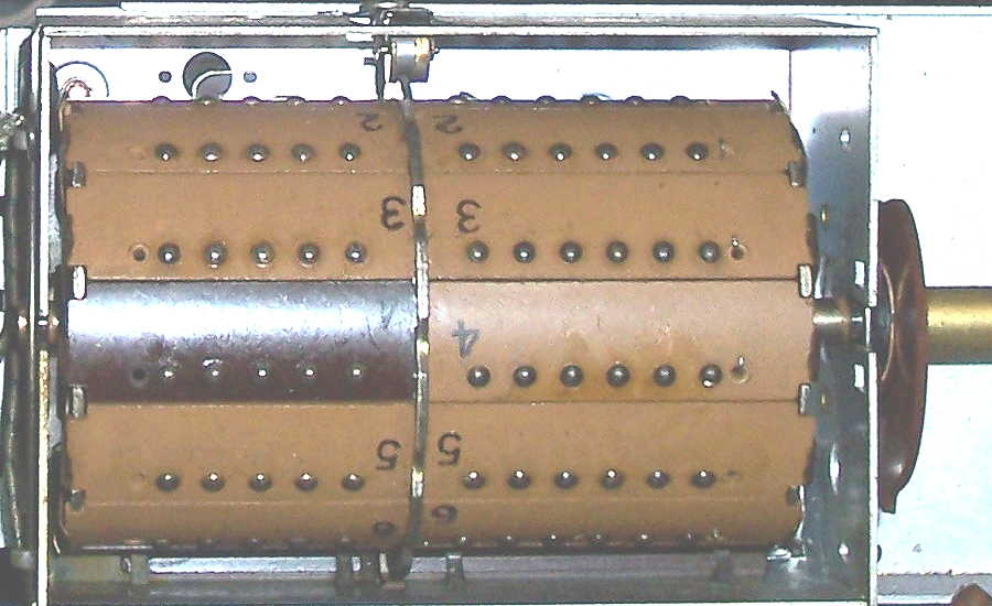
The chassis is transformer powered, electro-static deflection is used on the picture tube. The tuner is of the turret type (link below). The high voltage for the picture tube is derived from a Radio Frequency oscillator and HV auto-transformer instead of the horizontal oscillator/flyback transformer method.
Turret Type Tuner
The Intermediate Frequency circuit uses the Inter-carrier Sound System. In this system the Video and Audio signals are amplified together in the IF chain. The sound is picked off at the end of the chain and fed to the audio amplifier circuits. This method eleminates the need for a seperate audio IF chain thus reducing tube and component count. The only drawback to this arrangement in this set is, the picture contrast is controlled by varying the gain of the last video amplifier (V9). This not only varies the level of the video signal, but the level of the audio signal as well, so when adjusting the contrast the audio is also affected to some degree.
The chassis was removed from the cabinet and given an inspection, looking for any burned components or any other tale-tell sign of an obvious problem. Finding none, the set was brought up on the Varic keeping a careful and watchful eye on the ammeter and watching the chassis for anything amiss. All the tube filaments lit up and at full voltage there was somewhat of a raster and tuning to one of the local channels produced sound.
Since this was a good indication there wasn't a major problem, the decision was made to go no further until the set was recapped. The defelection circuits use several 6,000 volt capacitors. These were ordered and while waiting for their arrival, the electrolytics and other capacitors were replaced. By the time this was accomplished the hv capacitors arrived and they were also replaced.
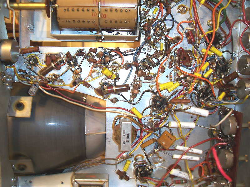
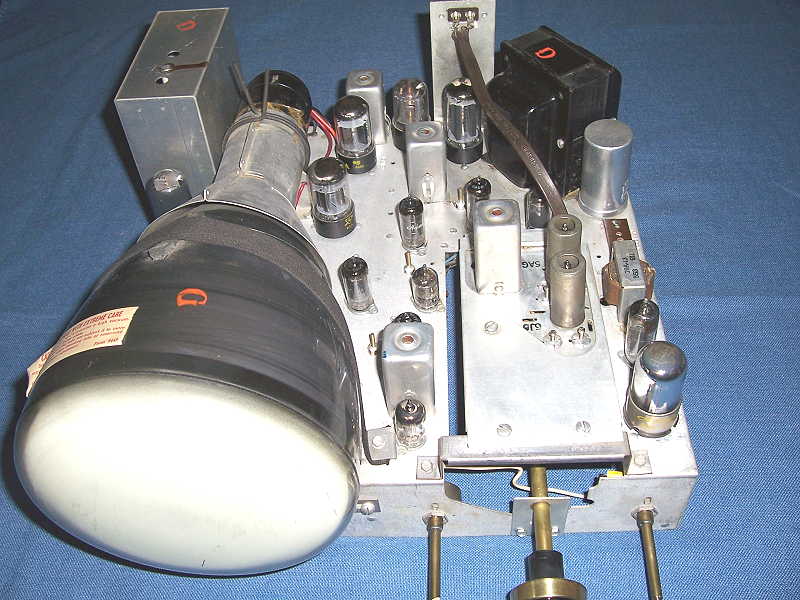
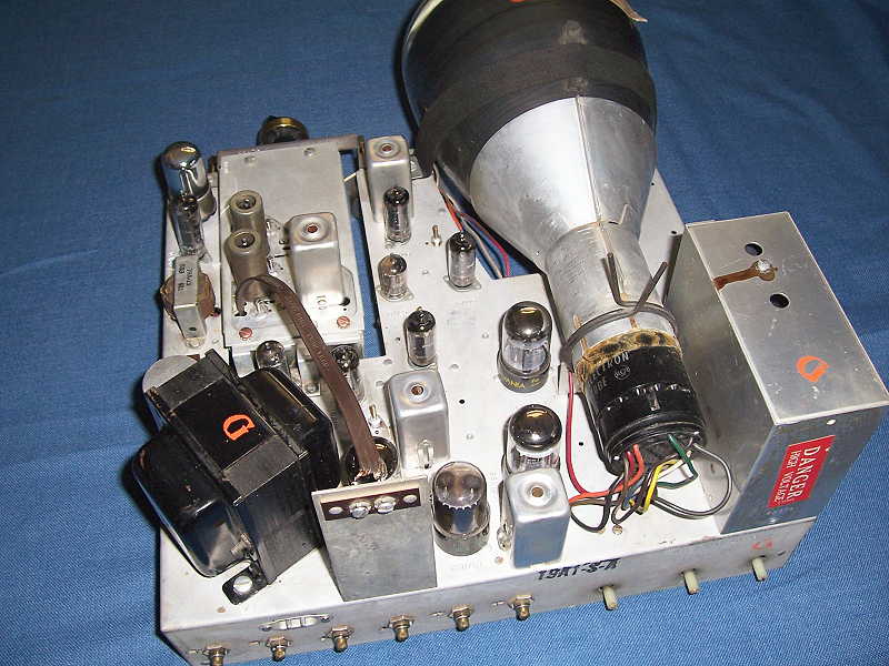
A view of the chassis after recapping
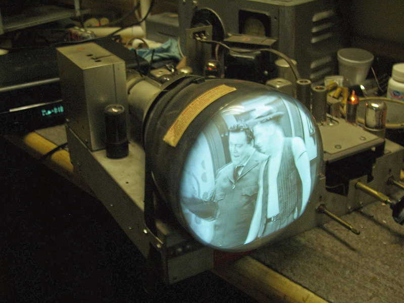
The chassis was once again brought up on the Variac, some quick measurements reveiled that voltages were in specs and with a few peliminary adjustments the results were quite good.
Capacitors replaced and nice picture
Next attention was turned to alignment. Alignment of the video IF is straight forward. A standard signal generator is used to stagger tune the IF circuits using the upper and lower frequencies of the bandpass (25.3 and 23.1 mHz). A VTVM is connected to a test point just after the 6AL5 detector and used as a peak indicator. After peaking the IF coils a sweep generator is connected and final adjustments are tweaked, using a scope, to obtain the proper bandpass and place the marker frequencies at the proper points on the waveform.
The chassis required very little in the way of cleaning. A damp shop rag and some elbow grease did a very good job of getting up a few years of dust and grime.
Chassis after cleanup
The cabinet had only minor scratches but was cracked along the upper side vent holes. Super glue was applied and clamps were used to hold until the glue set. One rear corner had a piece missing. Balsa wood was used to make a form and fiber glass resin was used to rebuild the missing piece. After the resin cured the balsa wood was sanded away and the area painted with black emamel. Novus #2 Polish and Scratch remover was used to polish the cabinet followed by a coat of paste wax to give it a good shine.
Click thumbnail for larger image