The
magical audio filter refined
and adapted for the Yaesu FT-301
by sv3ora
On the November 1983 issue of QST, Jim
Pepper W6QIF has released the "Magical audio filter". By reading at the article,
it seemed suitable as a companion AF filter for my Yaesu FT-301. This
circuit, while not the sharpest filter possible, offers quite a lot of
combinations to shape the AF signal accordingly and reduce noise, while
still being able to recover the audio intelligence. For a detailed read
of how the filter works, read the original article. Here I present my
modifications, which add more valuable features to the filter and solve
a series of problems in it that I have detected.
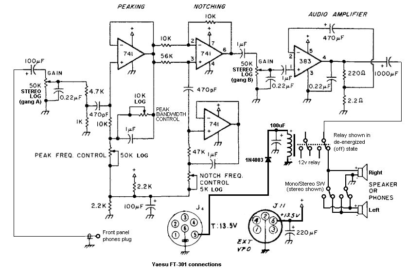
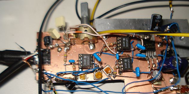
The complete modified schematic of the filter is shown above. After
finishing building the original circuit, I found that the bandwidth of
the peak filter can be varied too, so I replaced the switch and the 1K
in the original circuit with a 10k potentiometer. 10k is enough to
ensure the same minimum bandwidth as in the original circuit. When you
set this potentiometer to the maximum bandwidth, the peak filter is
essentially disabled. It's audio output volume is then the same as that
of the incoming signal. Based on the above findings, the peak switch
and the series capacitor are not needed anymore, I just set the
potentiometer to the maximum bandwidth to disable the peak filter. This
is a similar action to the one used on the notch filter.
Some potentiometers have been replaced with logarithmic versions so as
to make the settings more linear. You have to set these logarithmic
potentiometers to the correct "polarity" to benefit from this
modification. I have not checked the polarity on the schematic, so they
may appear backwards connected.
The filter works fine (no differences in volume or settings) with 13.5v
instead of 16v. This voltage is convenient because you can take it
directly from the FT-301 without the need for an extra power supply. On
other transceivers 13.5v (or 13.8v) is more convenient, as every shack
with a transceiver has one.
I have also connected one or two 8-ohm speakers in parallel at the
output, no problems driving them.
I have also added another capacitor at the input, to ensure that there
is no DC at the input potentiometer, since the FT-301 has some internal
resistors connected to the top of this potentiometer and I do not want
to interfere with them.
There is one thing I really did not like about the filter and this was
the hiss that was heard even when no input signal was present. Most of
this hiss comes from the filter stages, not the AF amplifier stage.
When I set the notch at high frequency this hiss is reduced of course.
I have replaced all the 741 with TL071 and the hiss was there. I have
tried 33nF in different places to ground as a crude hiss filter, but it
did not make any difference. Instead of altering the circuit, I decided
to use a stereo potentiometer for the gain control. One gang of this
potentiometer is connected to the input of the filter and the second
gang to it's output. That way, when the audio volume is set to low
levels, the hiss is also attenuated and becomes almost unnoticed. At
high audio volumes, the received noise overcomes the filter hiss anyway.
The bass response of the original circuit was not that good. This is
mainly the AF amplifier issue. I changed some capacitors in the AF
amplifier and now the bass response is much better, close to that of
the FT-301. I have also replaced the 470nF capacitors to 1uF, since
this did not make any audible difference, so one has to order only one
value of capacitors instead of two, when builting the filter.
When connecting the filter to the FT-301, power is taken from J11 on
the FT-301 and the audio source is taken from the front panel phones
plug. Initially I used pin 1 of the J4 connector on the FT-301 to take
the audio out. However, this had two disadvantages. First, the internal
speaker of the FT-301 was not disabled when the filter was connected.
Second, I noticed some weird audio hiss when I switched from TX to RX.
By taking the audio source from the front panel phones connector, both
of these problems were solved.
During TX, in some bands and at high powers, the filter/amplifier chain
was picking leaked RF (no it did not pass through the audio cable).
This RF was rectified at some point and the demodulated audio was heard
on the speaker. Instead of shielding the filter/amplifier chain, which
might be more unpredictable, I decided to add a mute circuit, which
would mute the audio circuit during TX. The simplest mute circuit and
one that worked very well, was to disconnect the speaker during TX
using a relay. The relay is controlled from the FT-301 by the pin 5 on
J4.
While this mute circuit worked well, it introduced another problem,
clicks to the speaker during the TX to RX switching. To solve this
problem, an adequate relay switching delay was introduced, using a
series diode and a parallel capacitor to the relay coil. The value of
the capacitor has been chosen so that it allows for enough delay for
the clicks to be muted, whereas allow for immediate audio un-mute
during the TX to RX transition. In very fast digital modes, you may
want to decrease the value of this capacitor if break-in operation is
desired, at the risk of not completely un-mute the clicks. For SSB
voice and CW the value chosen was proven adequate.
I like how the filter works and
with the
modifications I did, it is even better now (at least for me), as only 4
pots are needed and no bypass switches (no clicks introduced in audio
and no more holes at
the chassis etc). The very useful peak filter bandwidth control has
been added, the bass response has been improved, the hiss has been made
unnoticeable, the clicks have been removed and the connections to the
FT-301 have been optimized.
The peak filter is not super sharp i.e. you do hear for
example the rest of the signals close to the peak or further. However,
the peak is
pronounced, so you can use the gain control to reduce the peak back to
the same level, whereas at the same time attenuating the rest of the
signals. And when you use the notch you can reduce one of the unwanted
signals even more. I am not sure which way is better, a super sharp AF
BPF or a more "ralaxed" tunable AF BPF combined with a tunable AF notch
filter? To my view, if sharp audio filtering is the goal, it might be
better to be done at the IF stage, using a CW crystal filter. After
all, that's why CW crystal filters exist. Since most commercial
transceivers already have one, either built in or as an accessory,
there is no need for a really sharp AF filter.
As far as concern the filter section, a bit of warning. A sharp filter, either IF or AF, may sometimes cause
problems in operation. When for example you scan a band for CW signals
with this sharp filter enabled, you have to do it really slow, so as
not to miss out signals. Scanning the band really slow, increases your
chances of missing out signals. The cure is to switch to the SSB or the
wide AF filter and scan the band. When a signal is found then switch on
the CW or narrow AF filter and focus on that signal alone.
Alternatively, with the use of a filter such as the magical audio
filter, the rest of the signals are not attenuated by the peak filter,
so you can still hear them. But the peak is pronounced and when a
signal is centered to it, you can reduce the gain so that only
this signal is heard. These are two ways you can achieve the same
thing, so which one is preferred is really up to you.
However, the magical audio filter offers something that a CW filter or
an SSB does not offer alone. This is the ability to shape the audio
response, either when on narrow or on wide settings. The only shaping
that can be done on the FT-301, is with the "Reject" notch control.
When on narrow mode, the magical audio filter allows you to pronounce
the wanted signal and attenuate the unwanted one. The frequency of the
peak can be varied, in contrast to the IF crystal CW filter, where it
cannot. When on wide mode and depended on the bandwidth adjustment, the
tone of the received SSB audio can be varied, knocking out some
interference (and usable AF) at the bass or the high region and make it
easier to copy the signal. A similar effect is achievable with the IF
shift that some transceivers have. On this wide mode, interfering tones
can also be cut with the notch filter. For example there are sometimes
you have an SSB voice QSO and a annoying tone appears in the passband.
This tone can be cut with the notch filter. Also because the filter
does not attenuate the unwanted signals but just pronouncing the peak,
you can narrow the width of the peak quite a lot and still be able to
recover the audio QSO well, at a much more reduced fidelity, but at a
much lower noise levels as well.
Initially, I thought that a second notch filter would be a benefit in
pile-ups. However, there is no need for a second one, because the
FT-301 already has a noch filter. This notch filter works in the IF but
the result is an audio notch. By combining the IF notch filter of the
FT-301 and the AF notch filter of the magical audio filter, two notch
filters are available.
Another feature added was the
mono/pseudo-stereo capability. To use this feature, two speakers (or
headphones) are required. Even with the switch set to mono, I have
found that the usage of two speakers instead of one, is an improvement
in how the operator understands speech. With the flip of a switch, the
connections of one of the two speakers are reversed. This reverses the
phase of one of the speakers (the speaker cone diaphragm is moved
inwards instead of outwards). This phase reversal causes a stereo
effect to the ears when the operator is sitting at equal distances from
the right and left speakers. This is the most simple form of stereo
simulation. Reversing the phase of one of the loudspeakers tends to
spread out the sound between the two loudspeakers. I have tried this
with a pair of Realistic Minimus-7 die cast body speakers. The effect
is exactly as described. The sound previously (mono) originated from
the center of the two speakers and at the front of the operator. But
with the phase reversal the sound originates from the sides, close to
the operator and near his ears. It is difficult to explain the effect,
but there is a huge difference. In contrast to true stereo or pseudo
stereo that is based on frequency separation between channels, all the
signals/frequencies are present on both channels. It is just the source
point of the sound that been altered, from a central point at the
front, to two points, each close in to the operator's ears.
In general, the filter does an
overall good job, offering lots of
settings to play around, but at the same time without being so
difficult to tune.
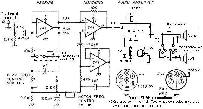
UPDATE 19-3-2020
Here is an updated version of the filter/amplifier. Another amplifier
chip is used and a special mute circuit has been combined so that the
mute relay is not needed anymore. A LPF at the speaker output composed
of a 1uF non-polar electrolytic capacitor and a 4R 2W resistor, takes
care of the hiss of the filter without affecting the AF tone much
Values of the filter for minimal effect on the wanted audio:
Speaker R C
4 ohms 5 ohms 10 uf
8 ohms 10 ohms 4.7 uf
16 ohms 15 ohms 2.2 uf
The resistor R should be as close to the speaker impedance as possible. I had two speakers connected
in parallel so the 4 ohms was the ones to use. However, I only had a
2.2uF non-polar electrolytic capacitor and a 10R 2W resistor available,
and these worked satisfactorily too.
The 50k peak frequency control
potentiometer must be connected like shown in the diagram (with the
wiper tied to the lower end), but in such a way where when the
potentiometer is rotated counter clockwise, then the peak frequency is
at maximum. Connecting it otherwise did not achieve an even spread
throughout the whole potentiometer rotation. This is really depended on
your logarithmic potentiometer curve, so a bit of testing is needed.
The 5k notch frequency control
potentiometer must be connected like shown in the diagram (with the
wiper tied towards the electrolytic), but in such a way where when the
potentiometer is rotated counter clockwise, then the notch frequency is
at maximum. Connecting it otherwise did not achieve an even spread
throughout the whole potentiometer rotation. This is really depended on
your logarithmic potentiometer curve, so a bit of testing is needed.
Back to main
site