A simple, good
quality UHF TV modulator
an old Elektor project
implementation and refinements by SV3ORA
This project
is presented only as a means of understanding the basic principles behind a tv
modulator.
Please consider your country regulations before building this project.
A UHF modulator build from scratch, is usually not a project for the beginner. The high frequencies involved, make construction critical so modern designs are all based on dedicated microchips to do the job. These microchips are all SMD, usually hard to find, making the construction difficult. Whereas these circuits work well, the simplicity of low-transistor-count modulators seems very challenging, even on today's standards. The truth is that, most of these simple circuits have really bad performance, making them rarely useable for more serious work.
The video modulator
Searching around the internet and many old magazines, trying to find better quality discrete UHF TV modulators, I found how difficult this proved to be. There are not many such projects out there, but eventually I found an old Elektor magazine article that describes a small promising modulator. The original article is shown below.
Before continuing reading this page, read carefully the magazine article. Below, I present you my implementation of the project, specific details of how to build it, as well as refinements that I made to the original circuit.
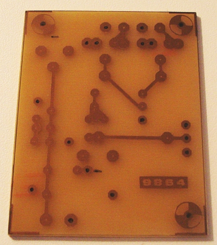
First of all, the article does not describe if the PCB should be single or double sided. By examining the PCB connections, one can conclude that the PCB must be double sided. The bottom layer of the PCB is full of copper, forming a ground plain. Most of the components should be soldered on the top layer of the PCB only, so no drilling is needed for these connections. However, some components have some of their pins connected to the ground, so PCB drilling must be done in these places. The places where drilling must be done, are shown in the next picture, noted by black marker dots.
As far as concern the tin plating of the PCB, do not attempt to do it. Tin plating with the soldering iron will increase the height of the PCB planar coils and alter their frequency response. Even tin-plating using chemical solutions, will affect the response and probably the Q of these coils, leading to poor stability. Just remove the photo-resistive layer from the PCB and leave the bare copper traces. Do this, immediately prior to components soldering. Avoid touching the copper and especially the planar coils with your hands, to prevent oxidizing them.
The article describes that the PCB should be grounded only to the RF connector and this connector directly grounded to the chassis. This means that the screws supporting the PCB to the chassis, must be plastic. Alternatively, you can use plastic insulators (like those used for power transistor heatsink insulation), to insulate the metal screws from the chassis and prevent them from making contact with the PCB bottom layer ground.

The picture above, shows my implementation of the PCB for the video RF modulator. I only had a scanned copy of the magazine so I had to do a little bit of image processing, to be able to clean the PCB image and print it at the correct scale. The correct scale PCB file is shown below.
PCB for UHF TV video modulator
Instead of the obsolete E310, use the J310 which is a direct replacement. For the two variable capacitors, I used 0.5-8pF types instead of 1.5-5pF, hoping to increase the frequency range of the modulator that way. I also did not have 10K potentiometers neither 3.9K resistors, so I used 22K potentiometers and 2.2K resistors. Since these components are there only to set the levels of video and audio to the modulator, it is ok to use other values and set the potentiometers accordingly.
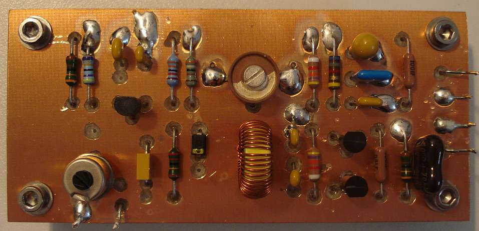
Notice the way the components are soldered onto the PCB. Since this is a UHF circuit, it is important to keep hot-end connections as short as possible. For example, if a component is connected from a planar coil to the ground, try to minimize the length of the connection to the planar coil side, and do not care too much about the length of the connection on the other grounded side.
Do not use excessive solder, use only the necessary amount of solder to solder the component rigidly onto the PCB trace. Especially L3, is very short and it must not be accidentally covered with solder.
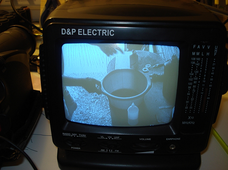
The picture above, shows the RF signal of the completed TV modulator in action, using a cheap B&W TV, located a few cm away from the modulator. In the video, played back from an old camera, my friend Ilias SV3ORF teaches me how to etch PCBs.
The audio section
Elektor magazine has published an update for the video modulator that allows to add audio as well, so both audio and video can be transmitted. The video modulator already includes an audio input, which actually accepts an FM modulated sub carrier signal, so no modifications to the video modulator need to be done.
Before continuing reading this page, read carefully the magazine article. Below, I present you my implementation of the project, specific details of how to build it, as well as refinements that I made to the original circuit.
Since the audio sub carrier modulator operates at much lower frequencies, it's construction is not critical. However, since the circuit operates at RF, I thought it would be better if I used a double sided PCB, etch the bottom layer as the magazine shows and leave the copper at the top layer, to act as the ground.
Of course, suitable insulation holes must be made to the top layer, so the components that are not connected to the ground, are insulated from the top ground layer. I made these holes using a larger diameter drill and carefully etching the top layer copper, taking care not to drill all the way through the PCB.
Again, I only had a scanned copy of the magazine so I had to do a little bit of image processing, to be able to clean the PCB image and print it at the correct scale. The correct scale PCB file is shown below.
PCB for audio sub carrier modulator
The interesting thing about this FM sub carrier modulator, is that it does not use a transformer like other circuits I have seen. This greatly simplifies design and makes construction easy, if a good components junk box is available at the lab. For the varicap I finally used a BB106, but I have also tried MV209 and other similar modern varicaps with much success.
Instead of a 7-70pF trimmer for C4, I used a standard 10-60pF that was available. Using this capacitor and a 10uH coil for L1, I could not tune the sub carrier down to 5.5MHz (the sub carrier at my country). Either a small 22pF capacitor had to be added in parallel with the trimmer or another coil had to be made. I thought that the stability and tolerance of commercial molded chokes is poor and their interference is higher than a toroidal coil, therefore I have decided to make a custom coil for L1, to tune to 5.5MHz. I wound 48 turns of enameled copper wire on an Amidon T50-6 toroidal core. I have chosen the 6 material for the core, because it is intended for the sub carrier frequency and it has a much better thermal stability. Another good option would be the T50-2. Also, smaller diameter cores of the 6 material could be used (adding a few turns more), but the coil wire would be thinner, so some mechanical support for the core might be suitable in that case.
Overal construction
A small aluminium
enclosure of suitable dimensions has been used to host the PCBs. The
audio modulator PCB has been placed vertically inside the enclosure to
save space.
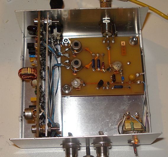
An aluminium sheet has
been used to mechanically support the audio sub-carrier PCB and shield
it from the video modulator. This effectively creates two small
shielded enclosures inside a big one. Some holes have been made to the
aluminium sheet, to allow for the cables to pass through, to reach the
appropriate connectors.
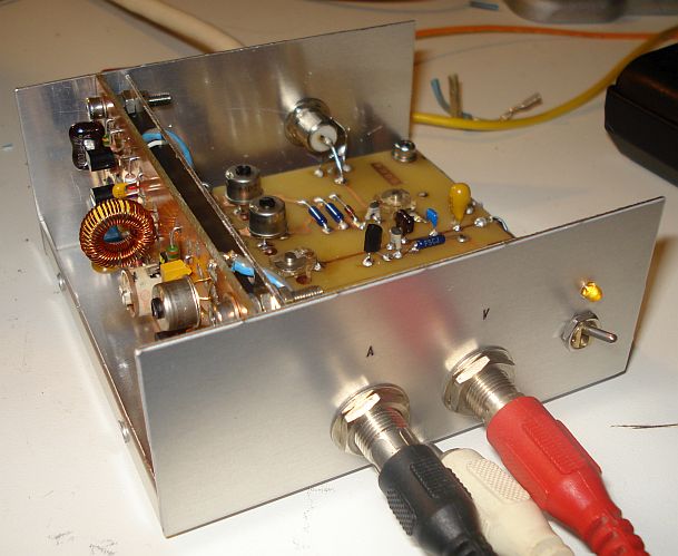
The connectors used
for the audio and video inputs are good quality ones made by
Switchcraft, whereas the on/off switch is made by Torbal. The high
efficiency indicator LED is driven at low current, using a 4.7k
resistor in my case, so that it is just used as an indicator and not as
a flashlight LED. The LED resistor has to be determined in your case,
depended on the specific LED you have in hand and the desired
brightness.
The power connector is
also made by Switchcraft. For the antenna connector, an F-type female
connector has been used, as this type of connector is a true 75 ohm one
up to 1GHz. The matching F-type male connector also eliminates the need
for soldering during installation to the coaxial cable.
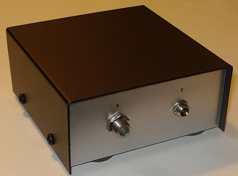
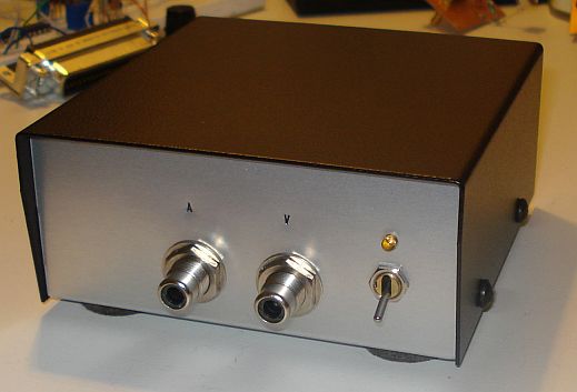
Punched letters have
been marked onto the front and back panels of the enclosure, to
indicate connections. At the bottom of the enclosure, four felt legs
have been soldered, to keep the enclosure firm to the desk below and to
prevent scratching the desk surface.