
The ultimate QRP HF
transceiver
During the last decades, there has been a great interest among QRP enthusiasts about building single transistor or otherwise really simple QRP equipment. Lacking the more sophisticated features of commercially available rigs and kits, these simple projects offer the user an opportunity to better understand the electronics associated with radio and at the same time develop operating skills, abilities which will remain with the user and form a good basis for furthering their understanding. The race is to develop low components-count circuits, with as many features as possible and minimum cost.
During my research in forums and over the internet, I came across the Gnat 1 transceiver. This single transistor transceiver takes advantage of the components in the circuit at their maximum. It uses a reflex receiver with applied regeneration, controlled by a quartz crystal and a crystal controlled power oscillator transmitter. I advise you to read the document, to understand how it works. Radio amateur experimenters, ought to try to improve things and publish their results. Having this in mind, I have decided to further improve the circuit and maybe add more useful features to it.
The first obvious improvement, needs to be the transformation of the circuit to multi-band operation. Initial component values are shown in the document for 80m, 40m and 30m bands and since the total components-count is low, it can be assumed that a separate transceiver can be built for each band. However, this doubles the number of components for each additional band. Examining the document, it is realized that apart from the quartz crystal, the band-depended components are T1, C3 and C4. There are two options for implementing multi-band operation. The first option, is to think T1, C3 and C4 as a block of components and switch a separate block for each band. This option requires less switches, but also an additional transformer to be built for each band. The second option, is to build a multi-tapped transformer. Whereas such a transformer is more difficult to build, only one is required for all bands, switched accordingly.
Reading at the document, it is proposed that a 1CT:1 transformer for T1, would increase the output power of the transmitter. However, the secondary of such a transformer, would have double the inductance and this has to be compensated by a suitable variable capacitor (C7), to tune to the desired frequency. Additionally, to preserve balance, all windings must be wound together at the same direction onto the toroidal core. Because of this requirement, for a 2CT:1, a trifilar winding is used, but for a 1CT:1, a quadrifilar winding is required and the secondary winding is formed by connecting two windings in series.
 |
|
|
|
|
|
D80 | A80 | |
|
|
|
|
|
|
|
|
|
|
|
|
|
|
|
|
|
|
 |
|
|
|
|
|
|
|
|
|
|
|
|
|
|
|
|
|
|
D40 |  |
 |
 |
 |
A40 | |
|
|
|
|
|
|
|
|
|
|
|
|
|
|
D30 | |
|
|
|
A30 | |
|
|
|
|
|
|
|
|
|
|
|
|
|
|
|
|
|
|
 |
|
C | |
|
|
|
|
|
|
|
|
|
|
|
|
|
E30 | |
|
|
|
B30 | |
|
|
|
|
|
|
|
|
|
|
|
|
|
|
E40 | |
|
|
|
B40 | |
|
|
|
|
|
|
|
|
|
|
|
|
|
|
|
|
 |
|
|
|
|
|
|
|
|
|
|
|
|
|
|
|
|
|
|
|
|
E80 | B80 | |
|
|
|
|
|
|
|
|
|
|
|
|
The picture above, shows the proposed multi-tapped 1CT:1 transformer. The letters represent the connection points and the numbers next to them, the band taps. Referring to the document schematic, point D is connected to C7, point E to GND, point A to C3, point B to C4 and point C to C2. The relevant taps, need to be connected to the transceiver circuit, according to the desired band. For example, if operation in the the 40m band is required, the A40, C, B40, D40 and E40 taps need to be connected to the rest of the circuit.
|
|
|
D80 | |
|
|
|
|
|
|
A80 | |
|
|
C | |
|
|
|
|
|
|
|
|
|
|
|
|
|
|
|
|
|
|
|
|
|
|
|
|
|
|
|
|
 |
 |
|
|
 |
|
|
|
|
|
|
|
 |
|
|
|
|
|
|
|
|
 |
|
|
|
|
|
|
|
|
|
|
|
|
|
|
|
|
|
|
D40 | |
 |
|
E30 | |
|
|
A40 | |
|
|
B30 | |
|
|
|
|
|
|
|
D30 | |
|
|
E40 | |
|
|
A30 | |
|
|
B40 | |
|
|
|
|
|
|
|
|
|
|
|
|
|
|
|
|
|
|
|
|
|
|
|
|
|
|
|
|
|
|
 |
 |
|
|
|
|
|
|
|
|
|
|
|
|
|
|
|
|
|
|
|
|
|
|
|
|
|
|
|
|
|
|
|
|
|
|
|
|
|
|
|
|
|
|
|
|
E80 | |
|
|
|
|
|
|
B80 | |
|
|
|
|
The picture above, shows the construction of the transformer in more detail. The document states that if a T37-6 core is used, the number of turns wound onto this core, would be as follows:
30m 12T (~430nH)
40m 15T (~680nH)
80m 20T (~1205nH)
However, the author suggests the use of larger cores for higher output power and in fact the PCB has been designed to fit up to T50-6 cores. To achieve greater output power and to make construction of the transformer easier (thicker wire size that makes taps easier), it was decided to use an even bigger core, the T68-6. However, the use of this larger core, means that the number of turns has to be scaled down, to achieve about the same inductance as with the smaller cores. The number of turns wound onto the T68-6 core, are as follows:
30m 10T (~430nH)
40m 12T (~680nH)
80m 16T (~1205nH)
To preserve balance, all windings must be wound together at the same direction onto the toroidal core. The easiest way to build the transformer, is to initially ignore the D40, D30, E30, E40, A40, A30, B30 and B40 taps and wind the transformer as it would only be used at the 80m band.
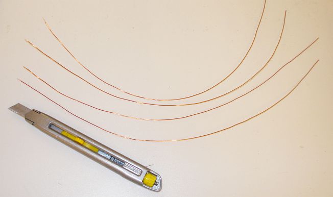
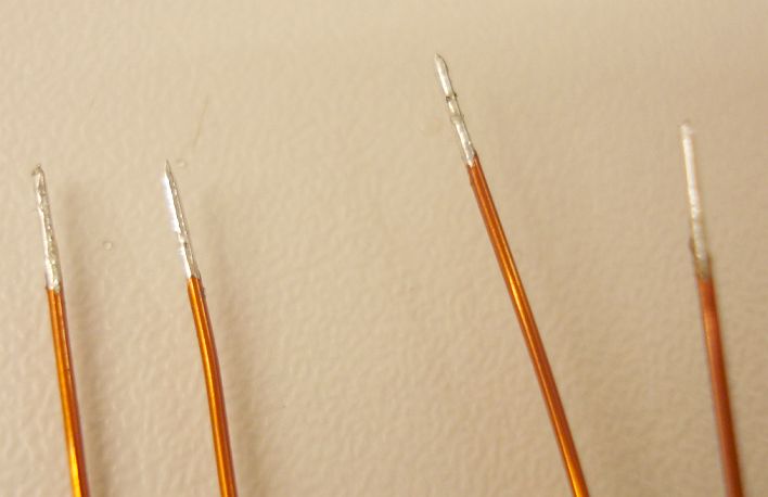

I advise you to use 4 different colors of enameled copper wire for the construction of the transformer. This will make construction much easier, than using a single color for all windings, as I did. Cut 4 equal lengths (~35cm each) of ~0.5mm enameled copper wire. Using a fine cutter, strip the enamel paint from their begins and solder them together. This will help keeping the beginnings of the wires together when winding. Then, holding all 4 wires on hand, wind 16 turns onto the core. After finishing winding, strip the ends of the wires and de-solder the beginnings. The final result, should look like the picture below.
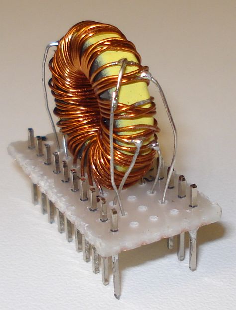
With so many wires, holding the transformer in place is difficult. For this reason, it was decided to mount the transformer onto a piece of proto-board, soldering the stripped ends of the wires to it. The joints that connect the relevant windings, are done below the proto-board.
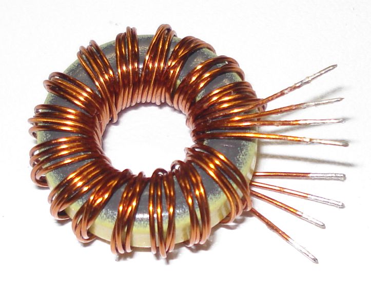
If you followed the procedure up to now, you have a nice transformer for 80m, soldered onto the proto-board. Now it is time to make the taps for the rest of the bands. The way usually this is done, is to carefully strip the relevant winded wires (at the outside surface of the core), at the desired number of turns, without cutting them and then solder a separate piece of wire on then. Then solder the other end of this wire to the proto-board, to complete the tap. Now you can probably see why using different colors for the wires of the different windings, makes construction much easier. The completed multi-band transformer is shown below.

A proposed pinout for the proto-board is shown below. Pin 1, 10, 11 and 20 are left unconnected and could be used for future taps in higher bands.
|
|
|
|
|
|
Pin1 | |
|
|
|
|
|
|
|
|
|
|
|
|
|
|
|
|
|
|
NC | |
 |
|
NC | |
|
|
|
|
|
|
|
|
|
|
|
|
|
|
|
D30 | |
 |
|
A30 | |
|
|
|
|
|
|
|
|
|
|
|
|
|
|
|
D40 | |
|
|
A40 | |
|
|
|
|
|
|
|
|
|
|
|
|
|
|
|
NC | |
|
|
D80 | |
|
|
|
|
|
|
|
|
|
|
|
|
|
|
|
E80 | |
|
|
NC | |
|
|
|
|
|
|
|
|
|
|
|
|
|
|
|
NC | |
|
|
A80 | |
|
|
|
|
|
|
|
|
|
|
|
|
|
|
|
B80 | |
|
|
C | |
|
|
|
|
|
|
|
|
|
|
|
|
|
|
|
B40 | |
|
|
E40 | |
|
|
|
|
|
|
|
|
|
|
|
|
|
|
|
B30 | |
|
|
E30 | |
|
|
|
|
|
|
|
|
|
|
|
|
|
|
|
NC | |
 |
|
NC | |
|
|
|
|
|
|
|
|
|
|
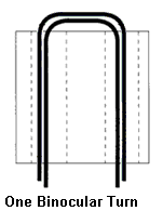
Transformer T2, is not a band-dependent component and it's construction is straight forward. Take two equal pieces of wire, ~0.3mm in diameter (#28-#30 AWG) and wind 4 turns onto the BN43-2402 binocular core (referred as 2843002402 in the document). All windings must be wound together at the same direction onto the core. The diagram below shows how one turn is wound onto the binocular core. To wind a second turn, repeat the procedure. All complete windings must end on the same side of the core. Watch out for the sharp edges of the core, as these can easily strip off the enamel paint from the wire and this may lead to short circuits between adjacent turns.

Do be continued...