The Vectrex logic board
The Vectrex logic board is the core of the Vectrex system, it is where all the functionality takes place. The rest of the boards are for power and driving of the screen tube. Reverse engineering of the Vectrex logic board definitely starts from reading the ROM, in order to be able to make a duplicate of it into an EPROM.
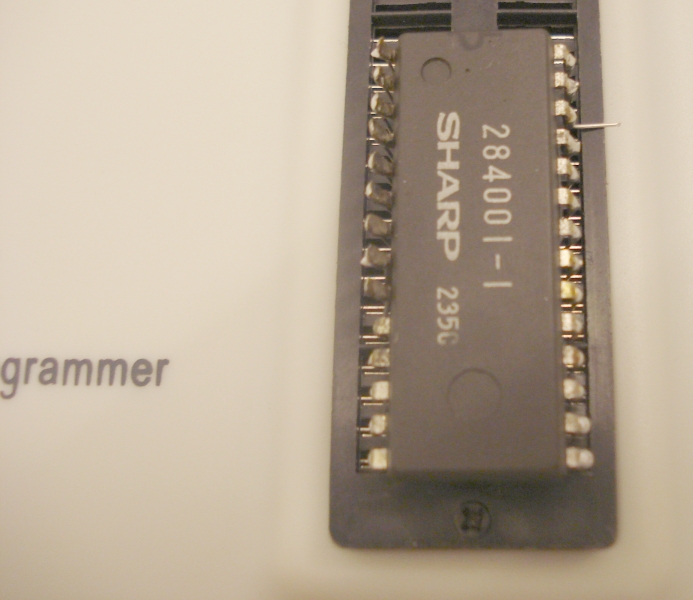
Reading the 2363 (8K x 8bit) ROM is not as easy as one may think. The ROM is soldered directly to the PCB and one has to ruin it in order to read it. There are two ways to do that. Use a de-soldering tool and de-solder the ROM or simply cut the pins. I have chosen the second way, because I did not want to take the risk of overheating a 20-years ROM. Even cutting the pins is not as obvious as you may think. You have to use a really sharp and small cutter, taking care not to damage the etched board.
After the pins are cut and the ROM removed from the logic board, I had to solder leads to extend the pins, in order to read the ROM on a reader. Hopefully, the 2363 ROM is a drop-in replacement to the 27C64 EPROM! So I setup the reader for the 27C64 chip.
First read failed! I was too disappointed, until I tried leaving pin 26 unconnected. Then I could be able to correctly read the ROM and save the bin file. Here is the original bin file for the Vectrex, as read from the ROM.
Download the Vectrex binary file here
Please give me some credit
for this, just refer my website. I have ruined my Vectrex to be able to make the
bin file available...
The Vectrex bin file can be written in a 27C64 EPROM directly. To verify that it works on this EPROM, I had to test it on the real machine. Having removed the ROM, I removed the remains of the cut pins and I soldered new socket pins, taken out of a spare IC socket.
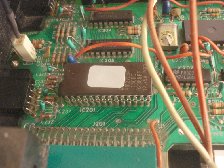
This is how the logic board looks with the programmed EPROM in place. All pins of the EPROM are in place, a drop-in replacement to the original ROM.
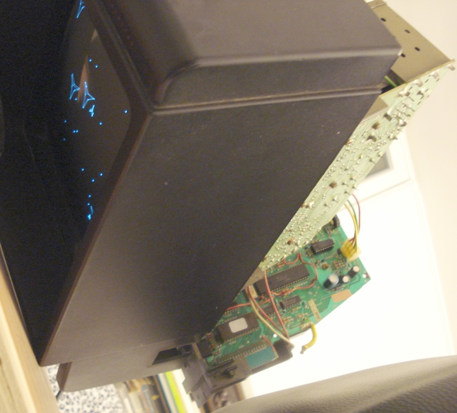
Picture above shows the Vectrex, with the EPROM installed and it is working perfectly ok. Success!
To be continued...