ZX80 chips reduction
The current page is not
complete! I am working on it right now.
Do not build anything on this page yet!
Further
hardware development of the ZX-80 on 2019? Yes! A ZX-80 with less chips
count? No way, the computer is already too simple to be simplified
more, one could argue. If they knew it back then, they would have
probably already done that to reduce cost even more. Or maybe the cost
of the LS series logic back then was not high, so it wouldn't worth it.
Or maybe computer-related people would not want to mess around with
discrete circuits. Who knows! The point is, that I begin to give an
answer to the disbelievers.
To reduce the chip-count of the ZX-80, an easy way I thought was to
replace the simple-gates ICs with discrete logic. This may initially
seem easy, but the thing is that it is not as straight forward as it
seems. The purpose of replacing the IC logic with discrete, apart from
fun, is to minimize cost and for availability reasons. For example you
may not have the particular chip on hand but you may have a few general
purpose transistors and diodes available. The key point is, that
complexity has to be kept in a reasonable level in this discrete logic,
so you cannot simply recreate the internal schematic of an IC using
discrete components. What you can do instead to keep complexity down,
is to use discrete components to mimic the behaviour of an IC gate at a
great extent, so the rest of the circuits of the computer will be happy
with it.
This requires a lot of testing and you have to test all the circuits
together working as a whole, not just bits. The gates I built, are
designed to operate correctly on this computer only, most of them
cannot be used as general purpose replacements for the IC types they
suppose to replace. Sometimes I made a gate and
then, when I made its surrounding connected gates, I had to alter or
re-think this particular gate to properly cooperate with the
surrounding gates connected. A particular problem I faced, was that the
gates inside an IC was used at different places in the computer
and connected with different external gates. So a particular
discrete circuit replacing a specific type of gate, may be suitable in
one place but not in the other without modifications. Also, note that
the three gates in the main clock of the computer have been replaced
with a discrete oscillator circuit, that uses the ceramic resonator on
the computer board as a resonating element. The output level of this
oscillator is rail to rail (0 to 5v) and it approximates a square wave,
so that the computer and especially IC9 is clocked nicely through the
C9/R2 integrator. So here is the
schematic I have ended up with.
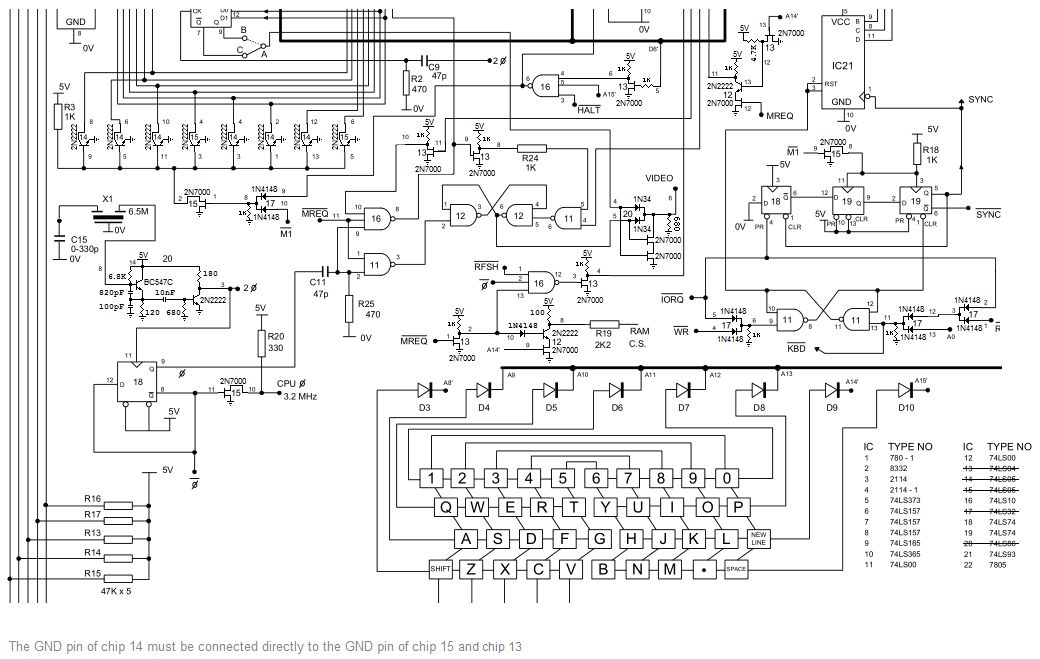
To be easy for you to follow the schematic and identify which circuit
replaces the relevant gate, I have drawn most the discrete gates at the
locations where the IC gates originally were. I have also left the
original IC numbers that the particular discrete gates refer to and
also the IC pin numbers that they refer to. The lower gate previously
connected in parallel to pins 11 and 10 of IC 15, has been removed.
Here is the full schematic of the computer, including the discrete
gates.
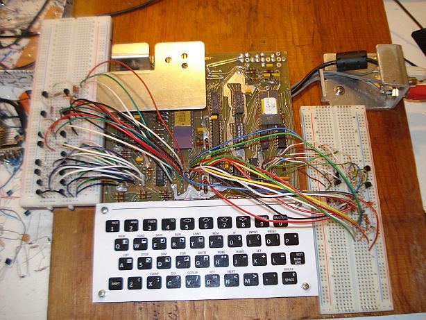
Below is the computer in gates-reduction testing.