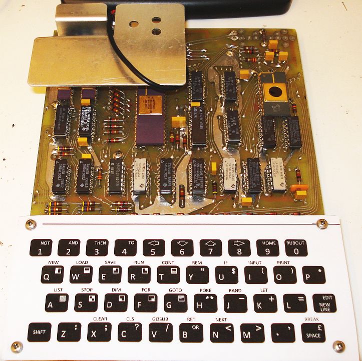
The ZX80 keyboard

I have decided to describe the ZX80 keyboard on another page than the motherboard mainly because it is a separate issue and can be built in different ways. My original thought was to use an external keyboard and rewiring it to match the needs of the ZX80. Later on, I thought that the real magic of such a single board computer is that everything resides on this board, including the keyboard. Also, rewiring an external keyboard is not such a pleasant thing to do, as it involves lots of point-to-point cabling. Thus, I decided to use the etched keyboard of the ZX80.
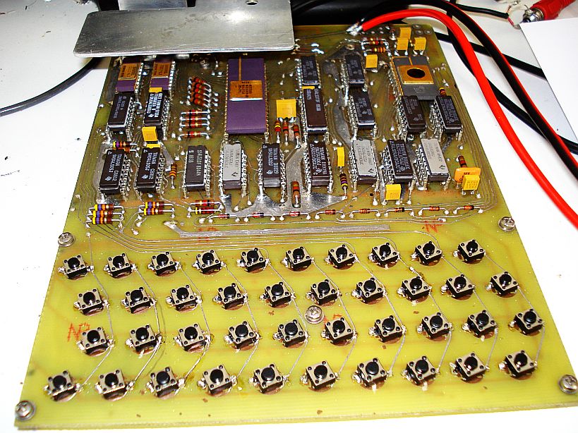
The ZX80 keyboard is a tricky thing to build. The original ZX80 uses a special membrane keyboard, mainly due to cost considerations. Martin has tried to build such a keyboard but I am not sure about it's reliability and it is not quite easy to build. Also, after some years, humidity can cause undesired effects on the critical keyboard contacts. Another issue which I have found quite annoying with the membrane keyboard, is that every time a key was pressed, I had to look on the screen, to ensure that this key is pressed indeed, as the membrane keyboard makes no sound when operated. To overcome these problems, I have found another alternative to the membrane keyboard, which is easier to build and far more reliable. I used standard miniature switches to bypass the etched keyboard contacts. You need 40 of them. These switches, when diagonally fitted, match perfectly the ZX80 etched keyboard holes. They also allow for soldering of both the bottom and the top layers of the PCB, connecting them together.

The only disadvantage of this technique, is that the switches are a little bit harder to press than the membrane keyboard. But at the same time, they make a characteristic "click" sound when pressed, which I have found to be very convenient. I no more had to look on the screen every time I pressed a key, to ensure that this key is pressed indeed, as I did on the original membrane keyboard. If you hear the key sound, the key has been pressed for sure. The application of more pressure on the keys that are closer to the center of the PCB, makes the PCB bend a little. To overcome this, I drilled an extra hole near the center of the PCB, as the picture below shows. A screw has been fitted there, which would hold the PCB steady to the enclosure, as well as the rest of the screws.
When all keys have been soldered, it is time to make the printed keyboard layout. I have made a slight modification to the original keyboard layout to allow for black and white higher contrast printing, even using an inkjet printer. I have found that in the original layout, some shifted annotations were included inside the keys, whereas some others (like shifted annotations on keys 1, 2, 3, 4, 5, 6, 7, 8, 9, 0) were outside the keys. All shifted annotations were originally in the same yellow colour to be distinguished. This leads to confusion on B&W printing. The layout I propose includes all shifted annotations inside the keys, at their top right corners. I have also brought the BASIC commands closer to the relevant keys, for better distinction.
ZX80 Keyboard layout (prints in correct scale)
Before printing, set your inkjet printer to use only the black cartridge for better results (more crispy images). When you have finished printing, you have to laminate the printout on both paper sides. Lamination on the bottom side, protects the paper from the switches below it whereas lamination on the top side, protects it from your fingers and makes the keyboard splash-proof. If you do not own a laminator, lamination can be done cheaply in any book shop.
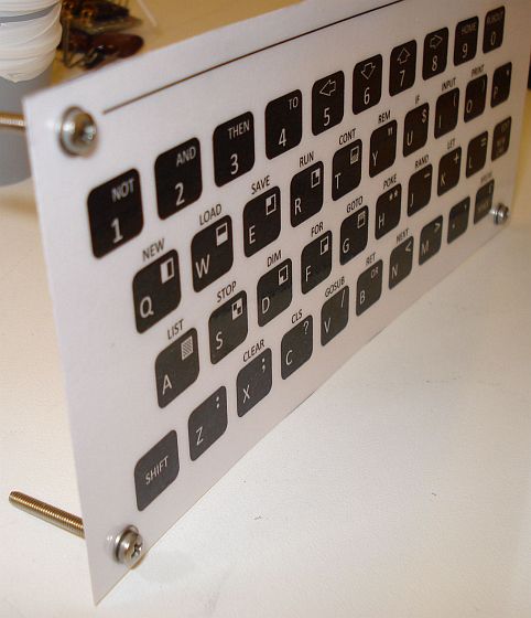
The next step is to fit the laminated keyboard layout to the ZX80. Cut the layout to the appropriate size and then cut four little holes at it's corners, to support the four corner keyboard screws.
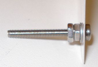
The extra screw that has been previously added at the center of the keyboard for rigidity, remains below the layout and you do not need to cut an extra hole on the layout for it.

The mini switches used, add a few mm of height to the PCB, which allows for this center screw to remain below their top surface. This extra height must be considered when fitting the layout to the four corner screws of the keyboard PCB. Use small spacers or nuts on these four screws, to keep the layout a few mm above the PCB. The height of the spacers depends on the height of the mini switches that you are going to use.
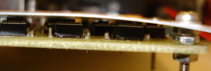
The whole process is easier than it sounds. Just make sure that you use appropriate spacer heights and that you cut the four corner holes on the layout at the right place, so that the center of relevant printed keys are just above (and slightly touching) the relevant switches. This ensures that the layout is flat along the whole surface of the keyboard switches and that when you press a printed key, the relevant switch corresponding to that key will be pressed.