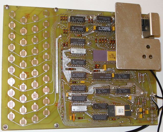
The ZX80 motherboard

One of the best websites around the motherboard is this one which provides almost everything about building the basic hardware. Grant Searle was very kind to grant me the permission to use some of the information presented on the current page. I will not reproduce the whole information from this website since it is there for you to read. I will focus more on the building process of the basic hardware and later on, on the different expandability options to build a complete useable computer, much more complete than the ZX80 was at the time.
The schematic of the zx80 is here. Another version (not tested) is here. I used this foil pattern, which is v1.1 to build the initial homebrew PCB. Grant Searle has done a wonderful job on it. It prints in correct scale on transparency. He has released other versions too, so look at his site if you are interested. I used version 1.1 because it is error free and it has been successfully built by Martin Lukasek too. Use an HP printer for printing the two transparencies and use HP transparencies if possible, for better results. The board is less than an A4 sized paper so photo-sensitive PCBs can be easily found. After having the PCB ready I noticed that some lines where cut, so I used fine wire to bridge the cut point and correct the error. Some cut lines are very tricky to determine, since the cut points cannot be noticed easily. It is better to put a torch in one side of the PCB and look through the opposite side carefully, so that the light can pass through the PCB and you can easily spot the tiny cuts in the PCB lines. Also a few too close lines were short circuited, so I used a sharp knife to etch the board between them and correct the errors. Because some lines are very close enough, an error may not be obvious at first time. Later on, as you solder each component on the PCB, check carefully for any potential errors near the component area, which will be easier to focus now. But there still may be some remaining errors, so check for any short circuits or cut lines using a multimeter before soldering the components. This is important if you want to have a working computer. All the errors I have initially spotted in my computer were caused by PCB faults. The PCB photos below, are the originals built and you will notice some errors on them if you have a closer look.


After drilling the board with different sizes of drills for different sizes of component leads, all areas of the board that have pads above and below each other must be connected together. Where this is a component, simply solder the top and bottom tracks to the component. If no component is to be placed at the hole then you will need to solder a wire through from the top layer to the bottom.
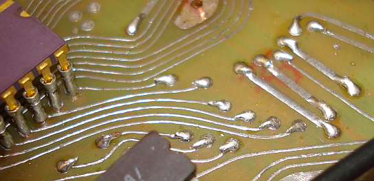
However, if you are going to engineer a suitable flat key panel, then obviously these connections need to be as low as possible on the top side. So, I would recommend, for these particular embedded keyboard connections, using a single strand of wire from a multi-stranded cable (only low current, so thin wire is fine) then press it flat against the top of the board before soldering. Solder the top side using as little solder as possible. Also, run solder over all of the key pad areas to raise them up a fraction. Then, if necessary, use a small file to flatten the soldered wires as close to the board as possible. I was going to use another method to build the keyboard for this computer, so I did not care about these connections too much.
Soldering the IC sockets are more problematic on double-sided boards as you
need to make solder connections to the top layer as well as the bottom. Using
normal sockets this will be impossible as the plastic on the socket would
obscure where you need to solder.
I recommend two ways of soldering the sockets:
Purchase wire-wrap sockets. These have very long pins so you will be able to mount the sockets a small distance from the board, allowing sufficient space to enable a fine-tipped soldering iron to complete the top layer solder joint.
(Cheaper option) Buy turned-pin sockets (better quality anyway) then use a pair of pliers to squeeze the plastic on the socket, breaking it and allowing the metal pins to be removed. Then, take a spare chip (or another socket), push these metal sockets that you have extracted onto the pins. You can then insert the chip/socket into the PCB as normal and solder the top and bottom track connections to the individual sockets. Then, pull out the chip and the soldered socket pins will then be neatly aligned and soldered. In fact I prefer this way as the quality of the pins is better and also there are no capacitive losses from the plastic of the IC socket (although these losses are not of much importance in such low frequency computer circuits). I have seen this technique in an expensive old Solbourne computer (Sun sparc clone) so I decided to go for it. The result looks much better than these plastic sockets. See the pictures below of how to do this.

Internal 1K ram in place. This shows how the chip socket pins are soldered. On the right, a typical example of a soldered resistor is shown.
Just for the beauty and rigidness of such an old piece of equipment, I wanted it to have fine components, so I tried to find some ceramic chips and carbon composition resistors. I tried to build a militarized version of the ZX80, so I looked for the military equivalents of the components used. Most of the components, including the semiconductors, the resistors the capacitors and the diodes is militarized. My basic ZX80 hardware version should be able to run on extreme temperature ranges as defined by the military standards. Of course this was just the way I wanted to do it but this was much more expensive. Ordinary, you can use any component you have, as the components are not critical in normal temperature ranges.
As I went through the component soldering process and having an original ZX80 side by side, I realized that some of the components in Grant Searle's component list are missing or are not correct values. They appear on the component layout though. Below is the corrected complete list of components, including the military equivalents I have used.
| Component No | Type | Qty | Mil./Indust. or better equivalent |
| IC1 | Z80A | 1 | Mostek MKB3880P-80 |
| IC2 | 2532 4K EPROM (*see text) | 1 | Ceramic side brazed version |
| IC3,4 | 2114 SRAM | 2 | D2114L-2 or D2114L3 Ceramic side brazed version |
| IC5 | 74LS373 | 1 | S54LS373F or SNJ54S373J |
| IC6-8 | 74LS157 | 3 | 54S157 or JM38510/30903BEA |
| IC9 | 74LS165 | 1 | SNJ54LS165AJ |
| IC10 | 74LS365 | 1 | DM54LS365J |
| IC11(*see text),12 | 74LS00 | 2 | SNJ54S00J |
| IC13 | 74LS04 | 1 | SNJ54LS04J |
| IC14,15 | 74LS05 | 2 | SN54LS05J |
| IC16 | 74LS10 | 1 | S54LS10F or JM38510/07005BCA |
| IC17 | 74LS32 | 1 | SN54LS32J |
| IC18,19 | 74LS74 | 2 | SNJ54LS74AJ or JM38510/30102BCA |
| IC20 | 74LS86 | 1 | SNJ54S86J |
| IC21 | 74LS93 | 1 | SN54LS93J |
| IC22 | 7805 | 1 | L7805ABP |
| D3-10 | 1N4148 | 8 | JAN1N4148 |
| X1 | 6.5MHz Xtal or ceramic resonator | 1 | |
| C1,2,4,5,6,12,13 | 47nF | 8 | M39014/01-1547 |
| C8 | 22uF | 1 | M39003/01-2380 |
| C9,11,14 | 47pF | 3 | M39014/01-1293 |
| C15(*see text) | 47pF (220pF on original board, 0-330pF is shown in schematic) | 1 | M39014/01-1293 |
| C10 | 1uF | 1 | M39014/02-1415V |
| R29, R37(*see text) | 180R | 1 | RC07GF181J |
| R35 | 1M | 1 | RC07GF105J |
| R1,3-12,18,22-24,27,30,34 | 1K | 18 | RC07GF102J |
| R20,32 | 330R | 2 | RC07GF331J |
| R21 | 220K | 1 | RC07GF221J |
| R2,25 | 470R | 2 | RC07GF471J |
| R19 | 2k2 | 1 | RCR07G222JS |
| R13-17,28 | 47K | 6 | RC07GF473J |
| R36(*see text) | 6.8K | 1 | RC07GF682J |
| Wire wrap cable for interconenctions | 5m | Tensolite Carlisle Co. Silver Coated Copper Wire 30 AWG Solid, White PTFE Jacket, 600V @ 200°C, P/N: 63111BD30BNN5 | |
| 40 Pin DIL socket | 1 | Round-pinned (better quality) version. Remove and use only it's pins, without the plastic | |
| 28 Pin DIL socket | 1 | Round-pinned (better quality) version. Remove and use only it's pins, without the plastic | |
| 20 Pin DIL socket | 1 | Round-pinned (better quality) version. Remove and use only it's pins, without the plastic | |
| 16 Pin DIL socket | 5 | Round-pinned (better quality) version. Remove and use only it's pins, without the plastic | |
| 14 Pin DIL socket | 11 | Round-pinned (better quality) version. Remove and use only it's pins, without the plastic | |
| Power transformer | Output: >8V to < 30V /1A | 1 | Stancor P-8617 wired for 24V/2A |
The parts placement can be seen from the component layout but it helped me to have a real ZX80 to compare. If you do not have one, here are two photos that can help you. This one is Grant Searle's ZX80 version and this one is my version.
A little note about IC11. None of my 54LS00 chips worked there, whereas my 54S00 chips worked fine. The 74LS00 chips worked fine too. This does not imply for IC12, only for IC11. I think is has something to do with the internal circuit of the 54LSxx or the brand I used, but I am not sure. Just have that in mind when using this chip for IC11.
In my version, there is a resistor soldered below the regulator heatsink and another one soldered parallel to the audio input plug, as shown in the pictures below. I have noted these two extra resistors as R36 and R37 respectively in my parts list. These are not included in Grant Searle's part list because his ZX80 probably did not have these. Also there is no printed component for these in the original board, but they seem to have been soldered there by the original maker.
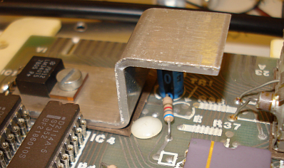
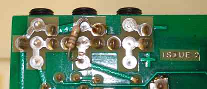
The purpose of these resistors is to increase the sensitivity of the audio input. Resistors R36 and R1 are used for setting bias voltage to the next stage. Bias volt. is 0.64V. LS series TTL integrated circuits used those days, had input low level 0.6...0.7V and high level 2.0V. So biasing near input low, gives more sensitivity for first stage (amplification and pulse former). To accomplish this, solder the resistors in place of the red lines in the picture below.

A word has to be said here about the EPROM used. The schematic circuit diagram refers to a ZX80 using the original mask-programmed ROM, which has a slightly different pinout than the 2532 (pin 21) and 2732. The EPROM Grant Searle uses in his original ZX80 is the 2532 (PDZ25P32-65JDH). Some brands/types of this EPROM cannot be used directly in place of the original masked ROM without rewiring! I did so, with the EPROMs I had available, and my computer booted ok, but I was not been able to use the 6,7,8,9 and 0 keys of the keyboard. It may be that these keys, that are also connected to A12 on the EPROM, are interfering with the normal operation of the machine. Below, on the left, is a picture Grant Searle sent me, that shows clearly how to connect this type of the 2532 EPROM to the circuit.
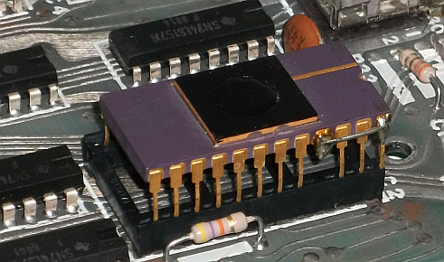
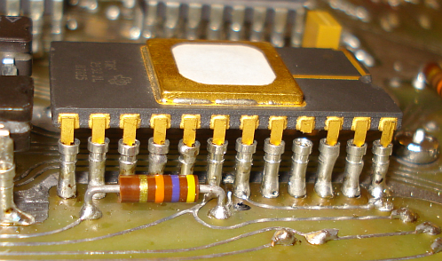
Pin 21 has been cut and connected to pin 24 (Vcc) using a small wire. It seems many EPROMs need Vpp to be connected to Vcc when operating "normally". Martin Lukasek did not do this rewiring at all and his computer worked ok. He did not use the ceramic side brazed version of the EPROM though, he has used the TMS2532JL, which has a black/brown ceramic DIP case. My EPROM, shown on the right picture above, is the TMS2532JL, with a ceramic side brazed case. I found that I did not have to connect pin 21 to the Vcc (pin 24), in order to solve the problem. I just cut pin 21 and left it unconnected, so that it cannot touch the socket pin below it. Problem solved!
Since you may encounter the same problem when building the computer and since it seems there are differences between 2532 EPROMs produced at that time, I am writing you the procedure you have to follow if you encounter the same problem. This will save you much time and it will ensure the minimum modification, regardless of your 2532 EPROM type. Please follow the steps below one by one:
If you use a 2764 EPROM instead, please read Grant Searle's page to see how to rewire it. If you use larger EPROMS please read at the very end of this page a discussion that I had in a forum. That is an old outdated page for this computer.
There is another issue about the C15 capacitor. My version and Grant Searle's version of the original ZX80 uses a 220pF capacitor. The schematic shows that a 0-330pF can be used. Grant used a 47pF in this prototype. I tested the effect of this capacitor value with both 74LS86 and 54S86 chips and the results are shown below.
Using the 74LS86 chip. Left picture 47pF. Right picture 220pF.
Using the 54S86 chip. Left picture 47pF. Right picture 220pF.
As it can be clearly seen, there is no noticeable difference either you use 47pF or 220pF. Please do not judge the quality of the oscillator from the images above. I used a single unshielded wire without any impedance matching circuit, to connect the oscillator to the oscilloscope. I just needed to see if oscillation would take place.
At this point I would like to present a tricky error that took me so long to figure out. On first boot the computer did not display anything on screen. After some checking I found that Pin 18 of the CPU (HALT) was always high, where it should give a square waveform. The PCB had a very small short circuit that I could not spot. Hopefully Martin Lukasek figured it out for me and the computer went alive on 30-6-2011!
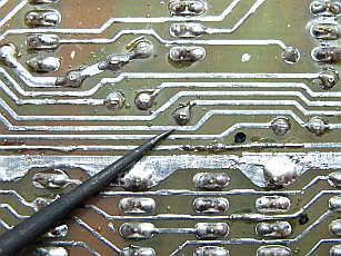
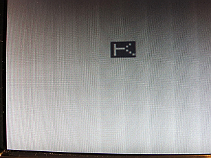
The problem was caused by joint between D6' and /KBD. Martin suspected a lot of other things before he finally found it. It behaved really strange.
Heat sinking was another issue in my version of the ZX80. The 54Sxx series components I used drew a lot of current and the total current the computer consumed was about 600mA, so the regulator went quite hot. A larger heat sink on the regulator is the price you have to pay for using these 54Sxx components. I have found the best heat sinks to be the ones that are composed of thin sheets of aluminum and allow for greater contact surface with the air. The thick heat sinks eventually concentrate the heat inside the thick metal and do not allow for good heat sinking. If you use the 54LSxx series instead of the 54Sxx you do not have to worry about the heat sink too much, as these are the low power versions of the TTL chips. Nevertheless, I would leave the big heatsink in place because the future addition of expansion cards will bring the current consumption from the regulator in higher levels again. The pictures below show the way the heat sinking is done. Note, a RAM pack is fitted on the ZX80.

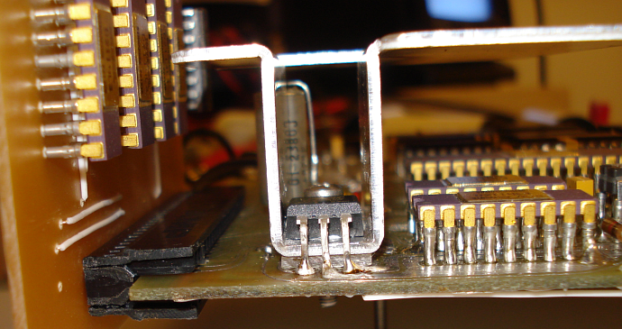
A big heat sink has been mounted onto the motherboard and extended upwards to allow for greater cooling. A small piece of PCB material, with no copper at all on both sides, has been inserted between the heat sink and the motherboard, to prevent the heat sink to short circuit the ZX80 bus lines that pass below it. A small hole has been done at the center of this rectangular piece, to allow the regulator mounting screw to pass through it and screwed on to the other side of the motherboard. The original ZX80 uses a thick piece of paper, which I do not find a good solution.
As of 7th of July 2011, I consider the construction of the basic motherboard complete. This is because I intended to use another method for the keyboard construction and the graphics interface. To test the motherboard at this stage, connect the composite video input of your TV to the ZX80, into where the modulator input signal should be connected. A "K" cursor should appear on the TV screen. This is an indication that the computer works, but the quality of the display image may not be good at this time. To correct this, you should build the graphics interface shown in another section of this page. Below are a few closer pictures of the motherboard.