Dual boot ROM
The ROM upgrade described in another article on this site is a nice little addition to the ZX80. But the disadvantage is that you need to unplug the EPROM in order to switch to the ZX81. Wouldn't it be nice to select between ZX80 and ZX81 in slow mode, using a single switch? That is the purpose of this special adapter described here. To make this adaptor, you need just one EPROM and a few pins and jumpers.
Components list:
| Component No | Type | Qty | Mil./Indust. or better equivalent |
| IC1 | 27C128 or 27C256 EPROM | 1 | WSI 27C128L-20 or SEEQ DM27C256-30 |
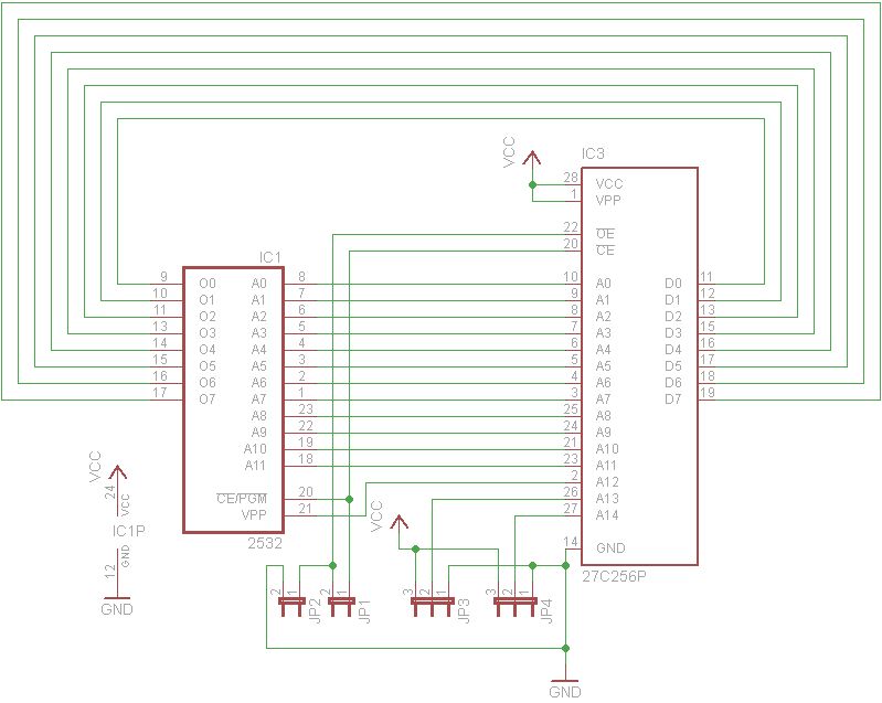
There are two options, use a 32K EPROM or a 16K one. The 32K EPROM contains the ZX80, ZX81 and ZXpand compatible images (ZXpand needs it's own modifications to the original ROM to work properly). The 16K EPROM contains just the ZX80 and ZX81 images. The related files for both options are shown below. Note that the schematic refers to the use of the 27C256 but an 27C128 can be used in place. The correct jumpers configuration is shown later on in this article.
PCB pdf file (prints in correct scale)
PCB artwork (Eagle CAD)
Schematic (Eagle CAD)
ROM image 32K (for 27C256 -
Contains ZX80, ZX81 and ZXpand compatible images)
ROM image 16K (for 27C128 - Contains ZX80 and
ZX81 images)
These files are Martin Lukasek's work, I just added a few alterations in the PCB to make it look more vintage, no other modifications.
Since I do not like the use of another computer (microcontroller) that the ZXpand uses and since it's source is still closed, I have chosen to use the 16K option (27C128), so the rest of the article will be based on this choice.
If you use the 27C128, you should connect pin 27 (/PGM) to +5V. This is JP4 in position 2-3 shown in the schematic picture. If you use the adaptor in the ZX80 (it can be used on the ZX81 too), then you should connect /OE and /CE to /CS. This is done by JP1 in position 1-2. Do not connect it to ground by JP2, no jumper there.
You choose the first or the second 8K bank of the 16K EPROM by JP3. If you have ZX81 image starting at the beginning of the EPROM, set JP3 to 1-2. If you have ZX81 in the second half, set it it 2-3.
To summarize, on a ZX80 using a 27C128 EPROM, the jumpers connections should be connected as picture below shows. The yellow jumper is used for the image choice and it is switched between 1-2 and 2-3 to select the appropriate image.

Instead of JP3 (yellow jumper), you can use a switch connected on the front panel of the enclosure that you are going to use for the ZX80, but remember: before you switch images you must power off the computer first. Alternatively you could use a double ON-OFF-ON switch, to ensure the computer will always be switched off before you switch to an image.

The 16K ROM image contains two
ZX80 images (to fill the bottom 8K) then the ZX81 image at the end. The ZX80 and
ZX81 images are appended together to make one 16K file (two lots of the ZX80
image plus the ZX81 image)
The memory map of the 27C128 EPROM is then as follows:
0 - 4K: ZX80 4K image
4K (4096): Beginning of ZX80 4K image (copy)
8K (8192): Beginning of ZX81 8K image
The main advantage of the adaptor is that you can easily chose between which
image to load, but it is not only this. By using a much newer type of EPROM you
gain much in access time. For example, the typical access time of an MCM68764C
EPROM is 500nS whereas 27C128 EPROMs can be found in access times of as low as
100nS. This is much of an improvement in speed.
The adaptor construction is straight forward. I used the same hollow pins as on the motherboard for the EPROM socket.
On the other side, I used the male pins of this type, to fit the adaptor to the ZX80 motherboard in place of the original ROM. A chip socket connected to the male pins, help them keep aligned when soldering them. Then you just remove the socket and you have a perfect alignment.
I have noticed that by using these pins, the adaptor firmly sits on the ZX80 ROM socket and there is no way it can be taken out without considerable force.
Also, these pins help the adaptor to stand a few millimeters above the near-by motherboard chips, which is needed indeed.
The whole construction is very rigid as shown in the pictures.