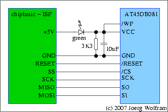
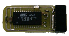
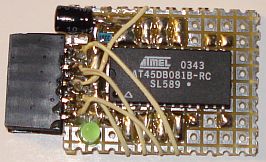
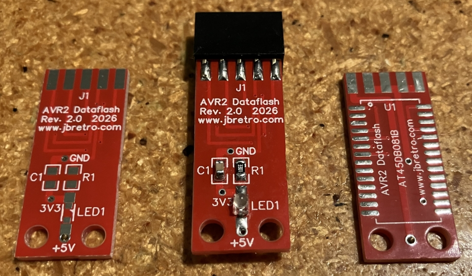
1 The Dataflash
module
1.1 Circuit diagram
1.2
PCB layout
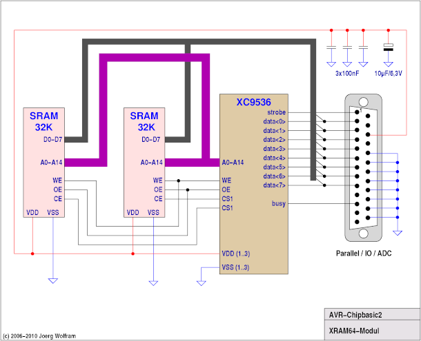
2 The 64K memory expansion XRAM64
2.1 Circuit
diagram
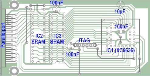
2.2
PCB layout
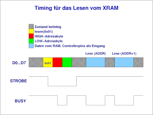
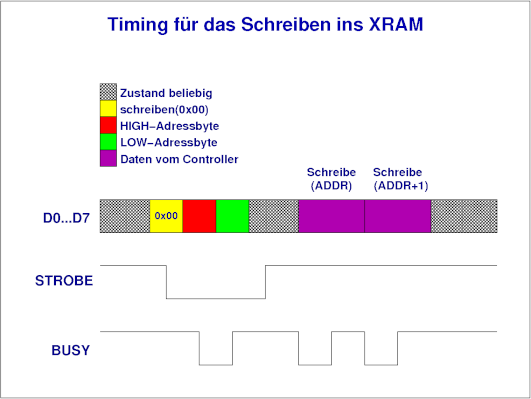
2.3 Control
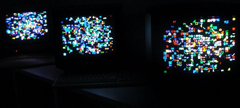
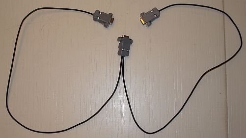
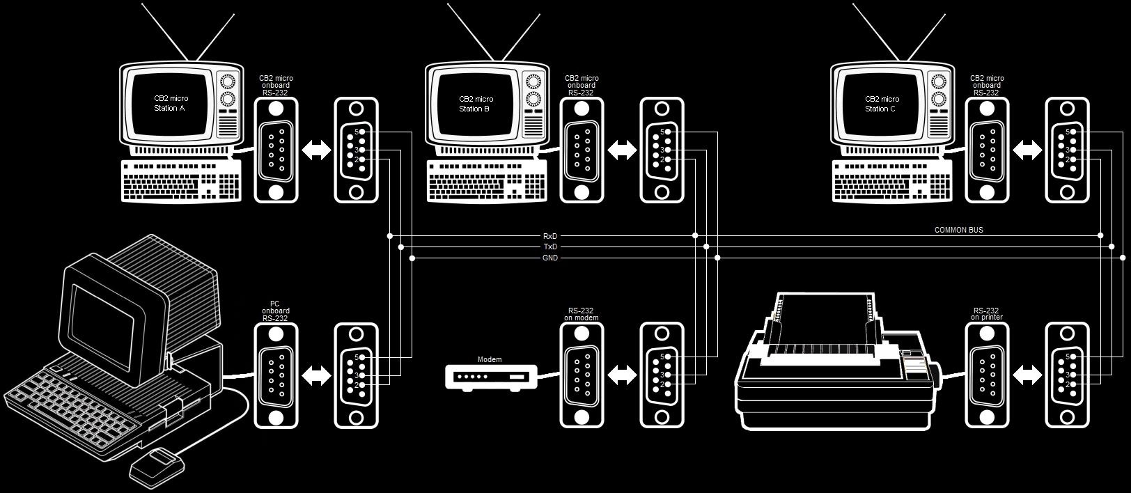
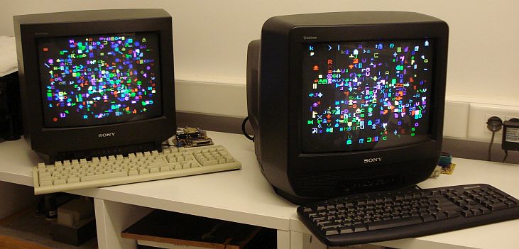
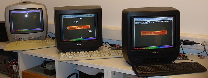
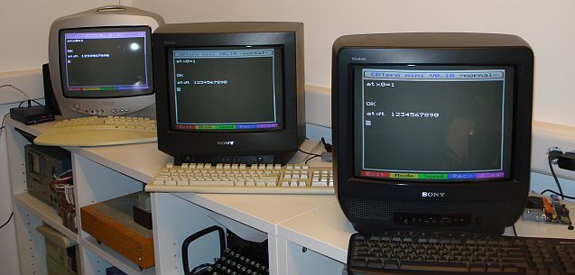
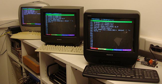
3 Local Area Network
3.1
How to build the hardware
3.2
Networking
examples
3.2.1
Connecting two CB2 micros together
3.2.2
Connecting three CB2 micros together
3.2.3
Connecting three CB2 micros and a modem together
3.2.4
Connecting three CB2 micros, a PC and a modem together
3.2.5 Connecting three CB2 micros, a PC, a modem and a serial printer together
3.3
Writing networked applications
4 External EEPROM
expansion
4.1 Circuit diagram
5 LPT connector
addition
5.1
Circuit diagram
|
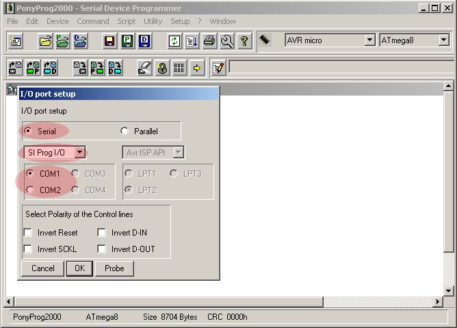
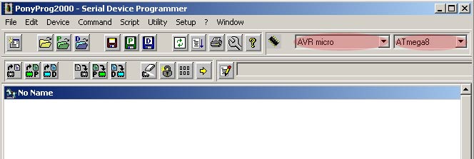
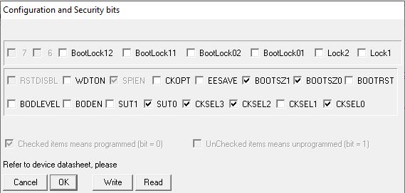
6 Reflashing the CB2
micro
6.1
Programmer circuit diagram
6.2
Reflashing procedure
7 Battery PSU
7.1
Circuit diagram
8 Color composite
video/S-video
8.1
Circuit diagram
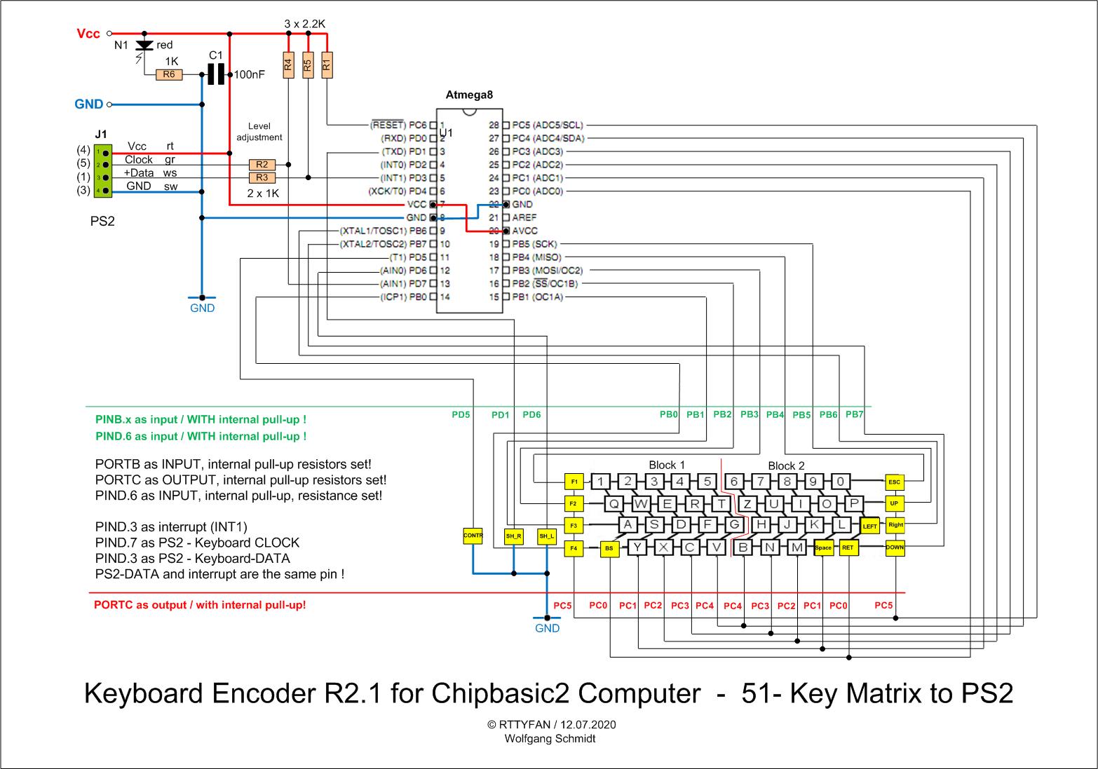
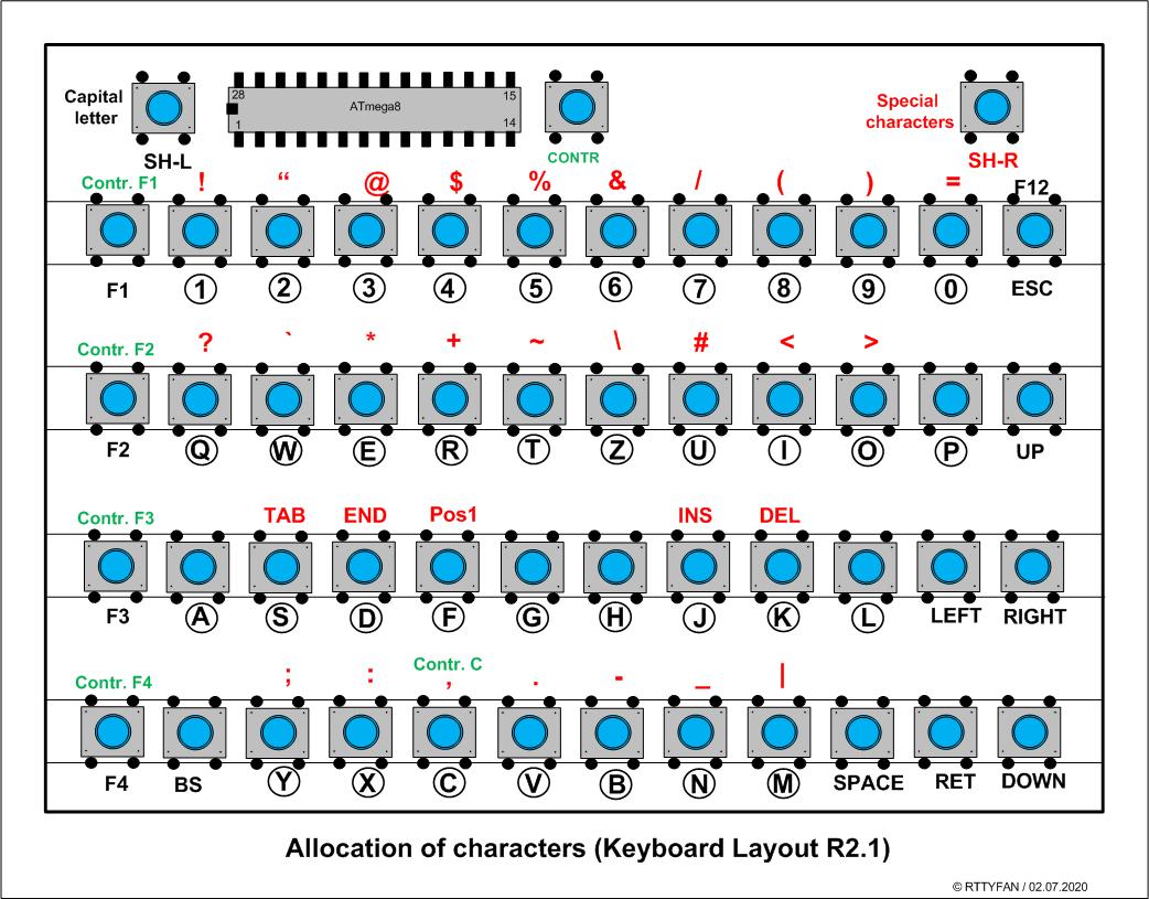
9 PS/2 keyboard
9.1
Circuit diagram
9.2
Firmware
10 3D printed case
10.1 Info and files
11 USB connectivity
11.1
Circuit diagram
11.2
Drivers
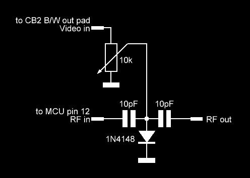
12 RF modulator
12.1
Circuit diagram
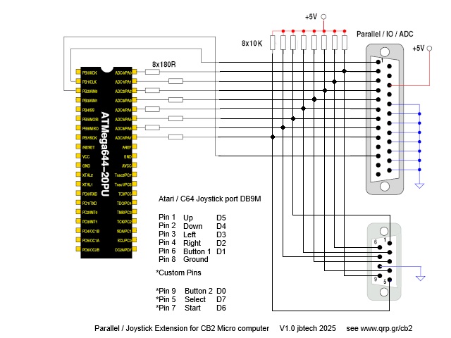
13 Joystick
13.1
Info and files
|