A single chip micro-computer for the lab
implementation by SV3ORA
Introduction
The idea of a simple single-chip useable computer inside a modern microcontroller was running into my mind for a long time. Eventually I found this wonderful project, which I decided to build. My goal was that everything should be simple and easy to make, so I have decided to build it using DIP chips, no SMD at all.
This is the second version of the single chip microcomputer I have built. The first version was built inside a keyboard, but this time I decided to go for a more proffessional look, using the original PCB and making my own modifications to it.
In this page, I
present some hints and tips to build your own computer from scratch. It
is basically a description of the problems I have encountered when
building it, so you do not have to reinvent the wheel.
Building the basic hardware
To build the project, first please read completely the author's website. There is no need to repeat this information here, it is already well documented. I usually keep local copies of the the project files in case the author's website goes down, so please contact me if you need them.
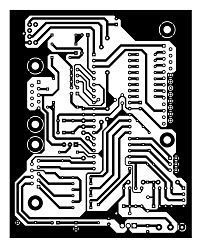
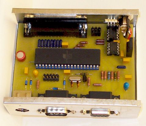
I have altered the original PCB layout so that only conventional components are used and no SMD types. I have also made a nicer look to the PCB, but otherwise all components places are identical to the original layout. Click on the PCB image above, to download a PDF file of the PCB artwork, that can be printed in real scale.
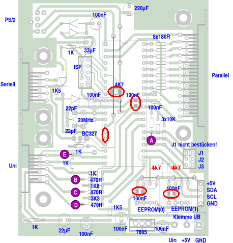
The modifications I
made to the PCB, are shown above in red colour. The SMD components have
been replaced by conventional types and 4.7k pull-up resistors are used
for the eeproms instead of 2.2k. There is no place onto the original
PCB for the 1uf capacitor shown
in the schematic, so this capacitor is ommitted. Also, there are no
pads onto the original PCB for the second serial port, so in my PCB
version I have included these pads in case you want to use it.
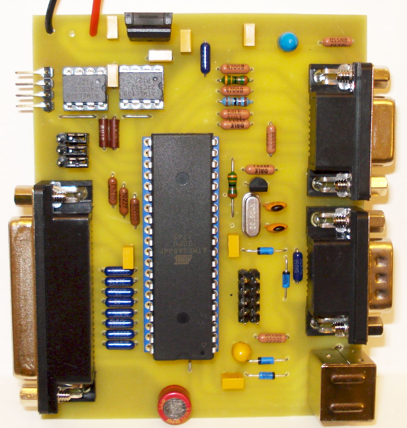
Click on the picture above to see a large version of my PCB. Note that a 4.7k resistor and a 100nF capacitor are hidden below the microcontroller body so they are not shown.
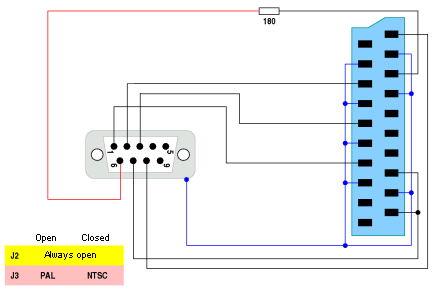
To connect the computer to the TV scart, for sound and color graphics, you need to build a custom cable adaptor. The author's website has an error on this adaptor. The correct schematic is shown above. The blue scart connector in the schematic, is shown as seen from the TV side (female connector on the TV chassis).
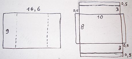
A suitable enclosure
for the computer, can be made by cutting two small pieces of aluminum
sheet to the appropriate dimensions. Then the sheets have to be bent so
that one of them closes to the other. The two pieces are held together
using screws. It is exactly the same technique that is used in most
commercial enclosures but you can make any custom dimension enclosure
by doing it yourself. The dimendions of the enclosure are shown below.
All dimensions are in centimeters.
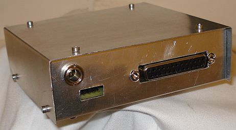
The holes for the
different types of connectors are made and then the PCB is placed
inside the enclosure. The PCB is held tightly to the bottom of the
enclosure using small screws and spacers. I choose to use a standard
power connector so that any type of jack wall transformer can be used,
as long as it can provide 8-30Vdc. This connector has to be mounted
onto the chassis and connected to the PCB using short length wires.
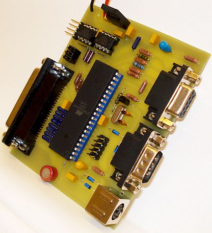
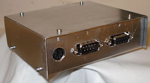
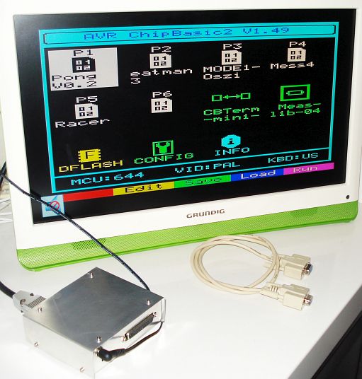
I did not include a power switch onto the
computer chassis. This has been done purposely, in order to force me
unplug the wall transformer from the mains plug when the computer is
not used. This not only saves power (a wall transformer forgotten
connected to a mains plug can cosnume power for months before you
notice it) but it is also more power safe. The completed computer is shown in the picture below. When used with a modern color TV, the colors are crisp and bright.
Loading programs to the AVR
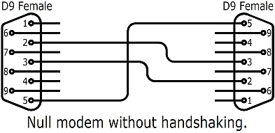
After
programming the microcontroller, to load programs to it, a null modem
serial cable is required. If one is not available, it can be built by
rewiring a standard serial cable, using the schematic below. Connect
this cable to the AVR and the PC serial ports.
Next, open HyperTerminal program in windows. Set the HyperTerminal com port settings as shown below. Then save and connect.
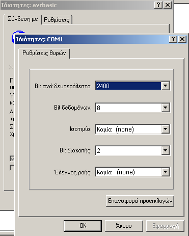
Next go to the CONFIG icon on the AVR screen and make the next settings:
Serial speed: 2400 Bps
Serial In/Out: simple
Serial Input: PD3
Save the settings and the AVR will reboot.
The
first program you need to load, is the kbd_us.bin, in order to set the AVR keyboard to US layout. Go to the
HyperTerminal and click transfer > send file. Select Xmodem protocol
and the kbd_us.bin file and then click Send. On the AVR, mark the program number on the AVR screen and
press CTRL+F3
to start the transfer. Once the program transfer has been completed,
press F4 on the AVR to run the program. Once the program has been run,
press CTRL+C and ESC to terminate it. The new layout is now set and you
may delete the program to save space by pressing CTRL+F4 on the AVR.
From now on, every time you reboot the AVR, the default layout will be
the US.
So far I have written about sending binary files to the AVR. If a text program listing is to be sent to the AVR, mark the program number on the AVR screen and press F1 to edit it. Then press CTRL+F3 to get into receive mode. On the HyperTerminal click transfer > send text file. Then select the text file listing to be sent.
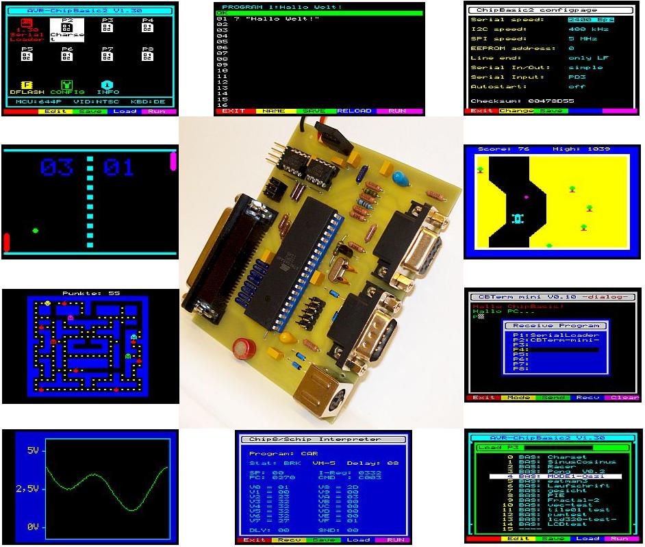
Program types
The microcontroller can run different program types. It can run native AVR programs and in emulation mode it can run AVR chipbasic2 programs, Chip8 programs as well as 8080 programs. Aside from the AVR native and Chipbasic2 programs that are provided by the author, click here to download many chip8 programs that can run on this system. These are not included in the original package. Note that you cannot download any Chip8 program from the internet and run it directly on the microcomputer, as it has to be first converted into a special format for the micro to be able to run. The author provides such a program, but I have already converted these Chip8 programs inside this package, so you do not need to do it by yourself, just load the programs to the micro to run them.
To
run Chip8 programs, firstly the Chip8 emulator has to be loaded into
position
P2 on the microcomputer screen and the library XMEM IRAM2 must be
loaded into position P8. Run the Chip8 emulator and while the emulator
is running, press F3 to load any Chip8 program from the DFLASH into it.
The Chip8 emulator can only load programs from the DFLASH, so if you do
not have a DFLASH installed, you cannot use this option.
Optional extensions
EEPROMS
My PCB version already provides space for two optional I2C EEPROMS (shown occupied in the picture), but you may omit them (as well as their 100nF decoupling capacitors and pull-up resistors) if you do not want the external memory option.
DFLASH memory
In the author's website, you will find the schematic for adding a DFLASH to store many additional programs for the microcomputer. This very usefull addition, allows you to store up to 255 programs inside the flash chip, that are available for instant loading into one of the eight positions (P1-P8) in the main microcomputer screen. It also allows you to save any program loaded or written in these positions, to the flash chip. The DFLASH works similarly to the HDD of a PC, allowing you only to load and store programs to it, whereas positions P1-P8 work as the main edit and run areas for your programs. If you want to run a program that is stored into DFLASH, you first have to load it in one of the eight positions (P1-P8). Also, note that the Chip8 emulator, allows only to load programs from the DFLASH.
Although the flash chip is SMD, it is very easy to solder by conventional equipment. The LED used, has an interesting feature. When any read or write activity is done on the DFLASH, the led brightness changes and it behaves both as an ON indicator for the computer, as well as a DFLASH activity indicator.
To be continued...