A mini dummy load for
impedance measurements
by SV3ORA
Reflection coefficient bridges, isolators or other devices, need suitable dummy loads to calibrate or operate correctly. Simple matching to 50 ohms, requires a single 50R shunt resistor, connected from the signal port to the ground. The properties of this resistor and the way that it is connected to the device, define the characteristics of the load. Furthermore, as frequency rises, these properties become more important.
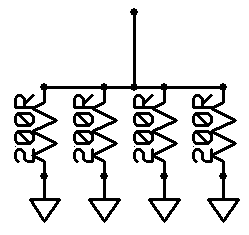
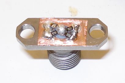
The 50R mini load shown here, uses precision SMD resistors, as a way to extend it's frequency range even more. Four 200R SMD resistors are connected in parallel, to achieve the desirable resistance of 50R and to increase the total power handling of the load.
The characteristics of the specific resistors used are shown below:
Manufacturer Yageo
Model RT0603BRD07 200R
Type Thick film chip resistor
Resistance Value 200R (200 Ohm)
Form SMD 0603
Size 1.6 x 0.80 mm
Tolerance 0.1%
Power Rating 0.1 Watt
Temperature Coefficient 25 ppm/K (TK 25).
Since each individual resistor can handle 100mW of power, the maximum theoretical load power handling is 400mW. However I suggest keeping the resistors much cooler, to prevent damaging and keeping the load resistance value precise. A rough estimation would be to keep the power below 100mW or so.
Mechanical design
Below, the mechanical design of the load is presented.
Vectorengineer CAD file
PDF file
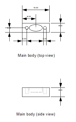
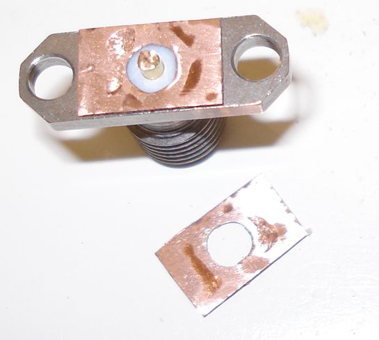
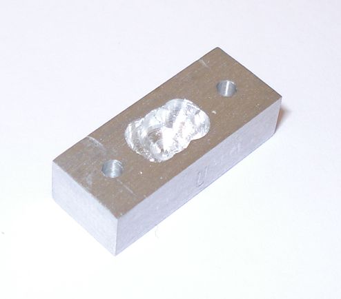
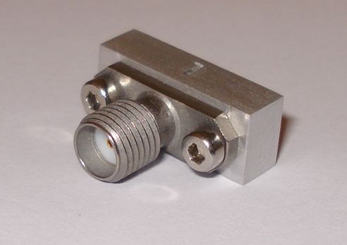
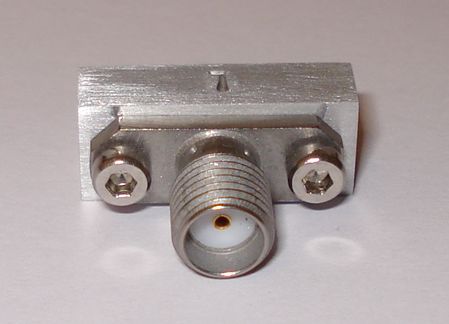
A small milled enclosure has been made and it's size is just enough to keep the SMA connector in place. Two identical loads were made, to be used in my reflection coefficient bridge circuit. To eliminate any differences in the bridge balance when interchanging loads, that could occur from possible differences in the characteristics of the loads, I marked the loads with L and U punched letters. The L load is always connected to the L port of the bridge. The U load is connected to the U port, whenever calibration of the bridge is needed, or when power measurements are made at port M.