AN/ULX-501 (Electrofile)
AN/ULX-501 (Electrofile)
James Dean, VE3IQ of Ottawa, gives a brief insight on developments beyond the UPD501 radar DF system. "When I was in the Electronic Warfare section of NDHQ in 1967 we developed an electric "pop-up" radar emitter identification system called the Electrofile (AN/ULX-501) for the IRE and DDH 280 class of ship. This was the first form of automation to speed up the process of identifying radar emitters. It moved the state of the art from operators having to look up possible emitters in a book (a really slow process) to a rapid presentation of a list of possible emitters given the frequency, pulse repetition rate and power level. This system then became the forerunner of today's CANEWS automated system. By far, the most prevalent emissions were in the X band and especially around 10 GHz. This was a very popular frequency because in the ITU Table of Frequency Allocations, there is a Radio Location allocation at 10 GHz. Due to the large amount of available equipment using klystrons and magnetrons, it was a neat countermeasures idea to bury warship navigation /surface radar in amongst all the commercial radars".For a more detailed look at Electrofile, select this link.
The UPD-501 was a High Probability Radar Early Warning directional finding receiver which was used to detect radar emissions on the SHF radar bands and gave some indication of the frequency in use, bearing, and the antenna rotation period. The receiver was connected to a horn antenna assembly which was mounted on the foremast and connected to the receiver by RG55/U coax.
| HISTORY
Robert Langille provides some background material. "The UPD-501 was registered as a JETDS device from 1952 to 1995. During its service life, there were three variants: * Variant 1 was fitted to the Tribal and Prestonian Class ships. - There were only X band horns fitted to a plate which sat atop the foremast. * Variant 2 saw service on the RCAF's Avenger AS3M, Lancaster MK X,
P2V7, Neptune (Temp), CS2F Tracker and also aboard HMCS Bonaventure.
* Variant 3 was applicable to the St. Laurent, Annapolis, 280,
and IRE class of ships. It was also found on Mackenzie
and Saskatchewan. Early fits in late 1950's may have been as Variant 2
but later evolved
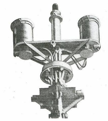
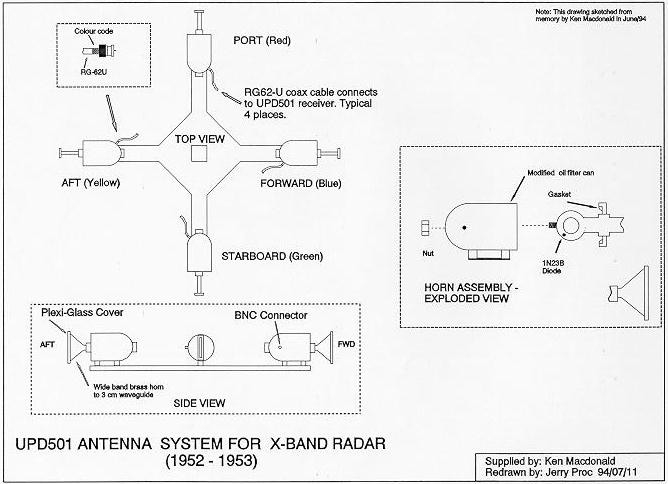
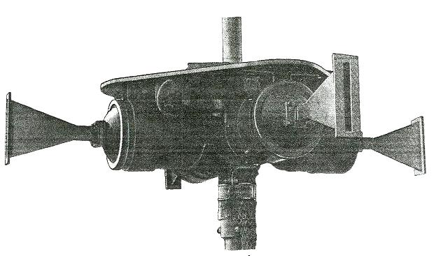
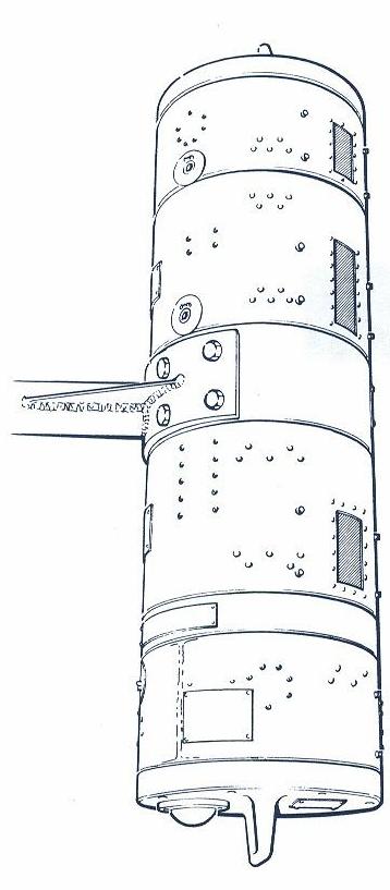
EMI Cossor produced the units for the initial procurement. During the 1960's EMI was acquired by Raytheon UK". In all these variations, nothing actually changed on the UPD-501 set itself. The addition of more than one antenna and the use of the antenna switching unit created the variants in the system. DESCRIPTION A UPD-501 was a High Probability Radar Early Warning directional finding receiver which was used to detect radar emissions on the SHF radar bands and gave some indication of the wavelength in use, bearing, and the antenna rotation period. The receiver was connected to a horn antenna assembly which was mounted on the foremast top and connected to the receiver by RG55/U coax. Initially, the UPD 501 horn antenna (circa 1953) was designed to monitor X band radar only. This was the version fitted on HMCS HAIDA and depicted below.
In the above diagram, 1N23WE diodes located in the antenna housing acted
as signal detectors. Changing these diodes could be a very interesting
experience in harbour, let alone at sea. In the 1970's, a two band version
(X and L) was introduced. Later, the antenna was redesigned for coverage
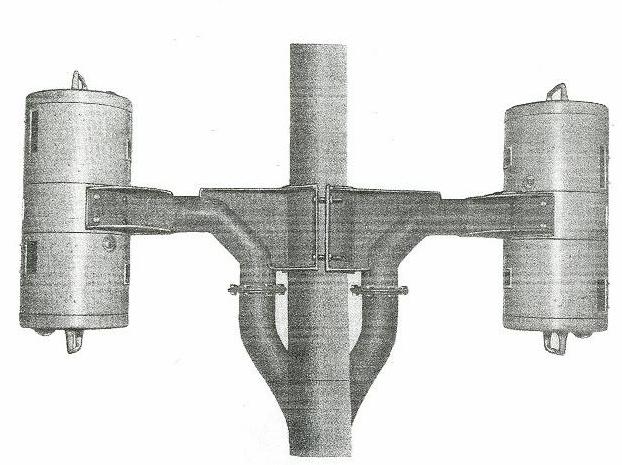
in three radar bands. The multiband version was a two piece, symmetrical
unit. Each vertical section was 34 inches long and consisted of four cylindrical
antenna modules that were bolted together. The original concept of the
"can" enclosure was devised by a RCAF engineer at Shearwater , Nova Scotia
while trying to fit the UPD to an Avenger aircraft in 1955.
The three band UPD antenna had the following coverage:
The design of the UPD501 was simple. In the set itself, there were four, wide-band radio frequency amplifiers, one for each of the antenna bearing angles. The outputs of the amplifiers would be applied to the four plates of a cathode ray tube and the relative signal strength caused a blip to appear on a CRT. This blip was appropriately deflected to visually indicate the relative bearing of the incoming signal. In the absence of any signal, a spot of light would simply appear in the centre of the CRT. Upon receipt of a radar emission, an audible alarm was also triggered. This alarm could be monitored by a loudspeaker or headphones. Pat Barnhouse, a former Electrical Officer and Radioman Special aboard HMCS HAIDA outlines a serious problem with the original UPD 501 antenna design and how it was rectified. "Our ship an inoperative UPD 501 set. It turned out that the crystal detectors in the horns had been burned out as a result of receiving an overload of RF from a nearby high powered radar, probably an SPS 10 or 12 sitting close to us in Halifax harbour. The problem was that there were no shutters on the original UPD 501 horns to protect the sensitive 1N23 mixer diodes and this burnout problem became endemic. Replacement was compounded by the horn placement on the bottom of that flat plate at the top of the mast extension, requiring a dockyard crane to effect replacement. The later multiband versions of the 501 came with the antennas mounted in "cans" that had shutters over the horn mouths. There was only one drawback to the UPD501 - it could not be used if the ship's own radar was operating. The UPD 501 system was still fitted right up to the mid 1990's however, it is not known if it was actually used near the end of its service life. |
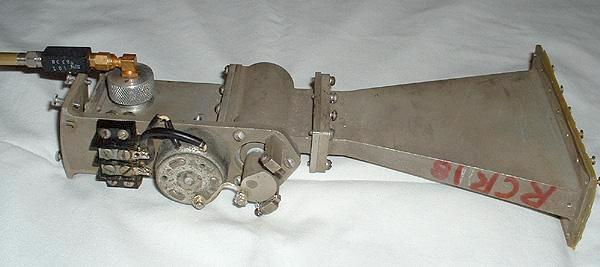 |
| Circa 1995: This X-band horn has been extracted from the AT-5007 "slice" of the multi-band UPD-501 antenna fitted to HMCS Mackenzie when she paid off. The portion in the center and left is a motor-operated shutter which when closed, would protect the signal diode against unwanted RF energy. 280 class ships employed a high power crystal in the horn which negated the need for a shutter, therefore the shutters were hardwired open as in this example. They also had a pre-amplifier right inside the can for the S and X bands. (Photo by Jerry Proc). |
Wes Short provides some details about the modifications to the horn antennas. "The horns were modified by having a "probe" machined at the Defence Research Establishment Ottawa (DREO) and having it placed in the position where the crystal diode would normally go (in base of the horn). There was also a frequency limiter between the diode and the probe. Testing in DREO's Anachoic chamber showed that the horns were a lot wider in frequency coverage then was specified so frequency limiters were added to the system in order to clear up some of the confusion. Only one set of these horns were modified and were initially trialed on HMCS Athabaskan (282) then extended to HMCS Fraser for further testing".
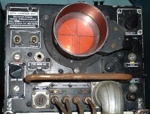 |
| UPD-501: The horn antennas connect to the front panel BNC connectors marked with Yellow, Green , Blue and Red dots. (Photo by Jerry Proc) |
 |
|
|
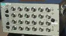
The UPD-501 could only accept signal from four horns at a time. To adapt it to a multi band environment, all the horns from a multiband antenna were connected to the antenna switching and control unit shown below. The operator would simply select the radar band of interest and the switch would select the correct set of horns. An optional speaker assembly could be attached to the '501 to monitor the pulse repetition frequency.
 |
| UPD501 antenna switching and control unit. This unit is provisioned with two antenna switching modules which can handle up to four bands. When in service, this one was used on the X, S and K bands.(DND photo provided by Robert Langille) |
Doug Stewart comments on radar band assignments." Prior to around 1975, we in EW, made radar intercept based on the WWII frequency band designators: S 2-4 GHz; C 4-8 GHz; X 8-12 GHz and K 12-40 GHz. The K band in particular, was divided into sub-bands: Ku 12-18 GHz ; K 18- 27 GHz and Ka 27-40 GHz.At this time, the above designators were standard to both military and civilian agencies. After the aforementioned year, NATO adopted its own unique band designators which were sequential alphabetic characters which incremented as the frequency increased. X band ceased to exist and became a function of I 8-10 GHz and J 10-20 GHz. K 20-40 GHz. In the photo of the UPD antenna control unit, the dymo tape indicating K band in company with X and S suggests a pre 1975 radar band designator.
RADAR BANDS [6] EU, NATO, US ECM Frequency Designations IEEE Designators A band 100 MHz to 250 MHz
B band 250 MHz to 500 MHz
C band 500 MHz to 1.0 GHz
D band 1 to 2 GHz
E band 2 to 3 GHz
F band 3 to 4 GHz
G band 4 to 6 GHz
H band 6 to 8 GHz
I band 8 to 10 GHz
J band 10 to 20 GHz
K band 20 to 40 GHz
L band 40 to 60 GHz
M band 60 to 100 GHzL band 1 to 2 GHz Long wave
S band 2 to 4 GHz Short wave
C band 4 to 8 GHz Compromise between S and X
X band 8 to 12 GHz Used in WW II for fire control, X for cross (as in crosshair)
Ku band 12 to 18 GHz Kurz-under
K band 18 to 26 GHz German Kurz (short)
Ka band 26 to 40 GHz Kurz-above
V band 40 to 75 GHz
W band 75 to 110 GHz
mm band 110-300 GHz
u mm band 300-3000 GHz
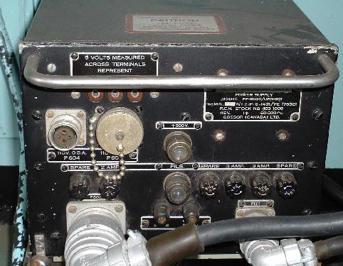
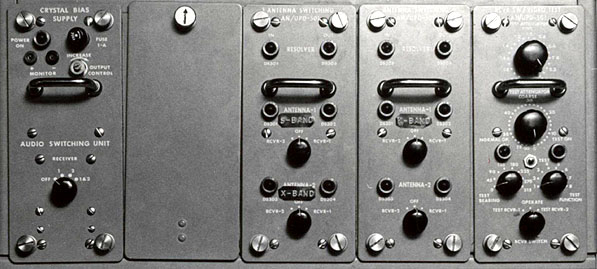
According to the JETDS nomenclature system, WLR means: W = Surface/Underwater Combined, L = Countermeasures, R = Receiver. Used primarily for electronic countermeasures applications, this receiver has a long history since it was introduced in the 1960's . During that time, many versions and upgrades were introduced. In its latest form it was much different in size, features and capabilities than when it was first introduced. Bob Langille provides an overview of the WLR-1 receiver.Robert Langille of EWCS provides an overview of the receiver. "The AN/WLR-1 family superseded the AN/BLR-1 (submarine version - circa 1953) and the AN/SLR-2 (Shipborne Version) receivers in the mid 1960's. The Royal Canadian Navy initially acquired the 1A model, then the 1C and subsequently the 1F models. Initial fits were partial on the St. Laurent Class and other Steamers. The 1F became the standard fit on the 280 IROQUOIS class and IRE Classes prior to being replaced by CANEWS (Canadian Naval Electronic Warfare System). It was also fitted to HMCS BONAVENTURE in her demising refit. Frequency coverage was from 50 MHz to 10750 MHz across nine bands. The 280's and IRE's had an extra band 9 tuner called the AN/SLR-503. However, once the USS PUEBLO was captured by the Koreans in 1968, the 1A variant was compromised and "most" of the system became unclassified. The US, Canada, Germany, HMS MERCURY and Australia used this system because it was ideal for Electronic Intelligence Collection. The US continued the development of the receiver by increasing the frequency range to 20,000 MHz. (ie the 1H model) and making it more solid state.
BANDS OF COVERAGE
The following list indicates which bands had omnidirectional reception only and which ones were both omni and direction finding.Bands 1 through 3 are covered by the AS-5048 (vertically polarized) or the AS-5049 (horizontally polarized), omni only
Band 1: 50-100 MHz
Band 2: 90-180 MHz
Band 3: 160-320 MHzBands 4 and 5 are covered by the Canadian DF antenna AS-5043
Band 4: 300-600 MHz (Omni and DF)
Band 5: 550-1100 MHz (Omni and DF)Bands 4 thru 8 are also covered by the AS-5050.
Band 6 through 9 are covered by the AS-899 Canadian DF antenna
Band 6: 1010-2600 MHz (Omni and DF)
Band 7: 2575-4450 MHz (Omni and DF)
Band 8: 4406-7375 MHz (Omni and DF)
Band 9: 7300-10750 MHz (Omni and DF)To assist in intercept, Canada also used an extra Band 9 tuner called the AN/SLR-503. This was fitted to IRE and 280 Class vessels. Frequency range: 7300-10750 MHz (Omni Only). The Canadian DF antenna was the
AS-899. In addition, two more variants were discovered on some RCN drawings.AS-5034. May have been the predecessor to the AS-5043. Bands of coverage are unknown at this time.
AS-5045. It is very similar to the AS-5050 but the cone is mounted on a short, circular pedestal. Bands of coverage are unknown at this time
In the USN, the 1H version which was fitted on most subs and surface vessels was superseded by AN/SLQ-32 and the AN/WLR-7 family. The WLR-8 and 10 was fitted to carriers and subs as well. The WLR-1 family was also fitted to certain classes of the United States Coast Guard (USCG) which used there own trained operators. I believe resource wise, there was great success in the USCG EW program as it took the stress of collection and correlation away from the military units. Because the Coast Guard was often in contact or dealt with the civilian population on a more frequent basis, it probably allowed them to concentrate more on commercial and pleasure craft radars and platform correlation than a US warship or submarine. Other countries are starting to realize this benefit and resource trade-off and are implementing EW systems into their own non-combatant programs. Because of our so-called unprotected coastlines, it is quite possible that we, as Canadians, could benefit as well".
 |
 |
|
| WLR-1H receiver. (Courtesy USS Nautilus web site) | WLR IP-480 trace simulation. PW= Pulse Width. PRF = Pulse Repetition Rate. (Graphic made by Robert Langille) |
The USS Liberty Inquiry web page provides a good general description of the AN/WLR-1 receiver in US service."In operation, the WLR-1 had a low probability of intercept and high sensitivity to signals within it's extremely wide frequency range (50 MHz to 10,750 MHz or 20,000 MHz with "band 10" installed). In other words, the receiver system was very sensitive; but due to its wide frequency range, it was dependent on the operator being on the right band, at the right time, to intercept a signal.
For radar signal intercept work, the WLR-1 system of 1967 era used a Cartesian (X,Y coordinates) display screen and not a polar coordinate (PPI radar-like) display. Each rotation of its spinning antenna would appear as a single line on the display. Each displayed line would contain a dot (or dots) indicating the frequency (or frequencies) of intercepted RADAR signal(s). After many antenna rotations and display sweeps, intercepted RADAR signals would appear like bars on the display screen.
When detecting radar emissions, the WLR-1 operator could manually select a specific frequency (signal) to analyze. It's spinning antenna would stop and rotate toward the direction of the signal source. Next, the display screen would be manually switched to analysis mode, allowing the operator to determine the exact frequency, pulse repetition rate, frequency jitter and other signal parameters. The WLR-1's high sensitivity allowed it to detect a radar emission at least 1.5 times the radar's operational range.
Generally, operating the WLR-1 involved a lot of manual effort, it was not as automated as one might think. There was a scan function that allowed automatic scanning of any one of its 9 frequency bands. But it was slow and, of course, this decreased the probability of signal intercept. It had 10 manually preset frequencies for quickly changing the tuner. These buttons were useful for tracking or revisiting a previously intercepted signal".
This diagram shows the placement of the WLR-1C antennas on the foremast of a 205 Class ship, Note the differences between the Band 1-3 antennas on the port and starboard sides. Both are omnidirectional but the starboard antenna is vertically polarized while the port antenna is horizontally polarized. Click to enlarge. (Sketch courtesy RCN) COUNTERMEASURES TRAINING
Robert Langille of EWCS provides a glimpse into countermeasures training. "The only UPD simulator that I am aware of was not an actual device. They were called Radar Receiver Exercises (RRX) and were instituted at some point prior to the mid 1960's.
These exercises consisted of a series of tapes with PRF (pulse repetition frequency) tones recorded on them. Operators who were in training, would listen to these tapes and they had to determine the pitch of each signal. Acceptable answers were either Low, Medium or High. This was the same format when reporting real intercepts with the UPD-501 since it had no way of determining the actual PRF in Hz. The wideband UPD-501, when collocated with the narrow band WLR-1 (50-10750 MHz) receiver, could be used very effectively together. Because of the wide bandwidth the of '501, it would alert the WLR operator of the presence of a signal. The WLR could, though the use of a frequency counter and oscilloscope, determine the PRF of the Signal of Interest (SOI). Later on, in the real environment, we acquired the Digital Pulse Trainer Sorter Analyzer (DPTSA) which when used with the WLR, provided an exact PRF measurement. The DPTSA could also measure Pulse Width as well, but in most cases it did it inaccurately. Around 1990, there was testing done on the UPD-501/DPTSA pair. It was not a success. As a result of excessive noise, an operator would have a had a hard time detecting any SOI or if there was even more than one SOI.
Also for training, we had the AN/ULQ-501 which was a EW Simulation System. This was a shore-based trainer located at Naval Annex Dockyard (NAD) in Dartmouth, Nova Scotia, right under the MacDonald Bridge. The setup resembled the 280 Class EWCR (Electronic Warfare Control Room) Console. Multi-Threat SOI's could be generated with this device. Training was fun and very realistic! The operator of the simulator was in the background and signals could be injected into both the UPD-501 and the WLR-1 receivers. In addition, seaborne simulation was either through NATO TRACSVANS (Transportable Radar and Communications Jamming and Simulator Vans) if available or Silverbox (Internal or External).
Many Maritime nations fully supported the TRACSVANS concept, since they could not indigenously or individually afford a sophisticated EW training capability, but could afford to acquire the capability on a collective basis. The US Atlantic Fleet Weapons Training Facility (AFWTF- pronounced AF WIT TIFF) was located in Roosevelt Roads, Puerto Rico. There was also a range in the Pacific on San Clemente Island as well, but not as upscale. Radar simulation was available to ships who participated on the range. AFWTF used both fixed and mobile sites. The mobile ones are called TRACSNAVS. The TRACSVAN concept is used also by NATO's MEWSG (Multi-Service Electronic Warfare Support Group) and the American FEWSG (Fleet Electronic Warfare Support Group) organizations as well. TRACSNAVS are basically ISO [1] shelters with an antenna farm. They can be found anchored down on the back of many vessels or hangar decks or even tankers to support EW training. It was quite expensive to run these types of ranges. Today, it is still utilized to some degree but the use of computers and software have largely taken over creating a less expensive, yet more sophisticated approach in teaching operators.
Silverbox was was a portable radar simulator that skilled operators used in order to train junior operators on signal recognition."
Operator's panel for the Silverbox simulartor. (Photo submitted by Robert Langille. Source unknown) Notes:
[1] An ISO shelter is one designed for the military to ISO standard 1496/1.
Contributors and Credits:1) Robert Langille <ewcs(at)ewcs.ca> Electronic Warfare Consulting Services http://www.ewcs.ca/
2) TRACSVANS http://www.manw.nato.int/manw/pages/update/envision_1_04/mewsg.htm
3) USS Liberty Inquiry web page - http://www.usslibertyinquiry.com/forums/showthread.php?t=1025
4) Wes Short <wsshort(at)eastlink.ca>
5) Douglas Stewart <dougjoy(at)ns.sympatico.ca>
6) Radar Frequency Band assignments http://www.reference.com/browse/wiki/Radio_frequency